Titan – AN8: Implementing a Modbus RTU/TCP – SNMP Gateway

Looking for something else?

Titan – AN8: Implementing a Modbus RTU/TCP – SNMP Gateway

Scenario Details

The Titan routers include all the typical features of a 2G/3G/4G router. However, they also include a series of additional features that help make it one of the leading market routers based on the number of features it includes.

One of these additional features is the ability to create SNMP (v2) connectivity for any Modbus RTU or Modbus TCP device, through which carrying out SET/GET operations, as well as sending traps upon changes in register values or status, is available.

In this Application Note an example will be used to show how to configure the Titan router in order to create this capability for a Modbus RTU device.

Description of the Example

In this example we will use a device with Modbus RTU communication protocol via its RS232 port (configuration: 9600,8,N,1). The Modbus device has as its Modbus address the value @1 and contains 33 Modbus registers for both reading and writing (numbered from 0 to 32).

We will also have an SNMP v2 server, from which we must be able to send GET SNMP commands at any time in order to any of the device’s Modbus RTU registers. We must also be able to use SET SNMP commands to change a Modbus register in the device. Finally, we also require that a TRAP is sent to the SNMP server to inform of any change in status for the Modbus registers 2 and 10 since these represent alarms.

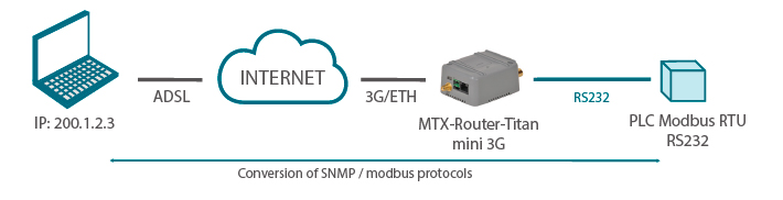
For this, we will use the MTX-Router-Titan-3G-mini router which is habilitated to carry out SNMP-Modbus protocol conversions.

SNMP Configuration

The first thing we must do is configure the SNMP section of the Titan router. For this, we must access the menu “Other > SNMP”, where we can activate the SNMP service and specify the UDP port and community for the SET and GET SNMP commands. The same is necessary for the sending of TRAPS, with the additional requirement of specifying the IP address used to send them.

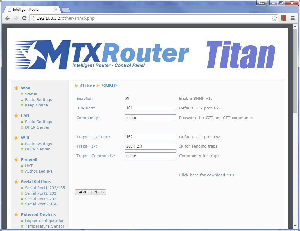
In the screen above, we can see a link marked “Click here for download MIB”. By clicking this link, the MIB database will be downloaded which includes information about the OIDs, TRAPS, etc.

Configuring the Titan Router’s COM1 Serial Port

We will use the Titan’s COM1 port to access the Modbus device containing the RS232 port. The necessary configuration, to be inserted in the menu “Serial Settings > Serial Port1-232/485”, is shown in the screen below.

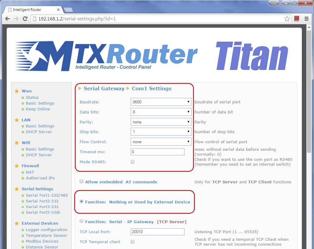
In summary, we must configure the Titan’s COM1 port to RS232 mode, using the same configuration as the port contained in the Modbus device (9600,8,N,1). The mode to be selected is “Function: nothing or Used by External Device” since the port will be used by the external Modbus device.

Configuring the Titan Router’s Modbus

This configuration is done from the menu “External Devices > Modbus Devices”. In the main part of the screen, we must select “Enabled” as well as indicate the COM1 serial port to read the Modbus, as we configured in the previous section.

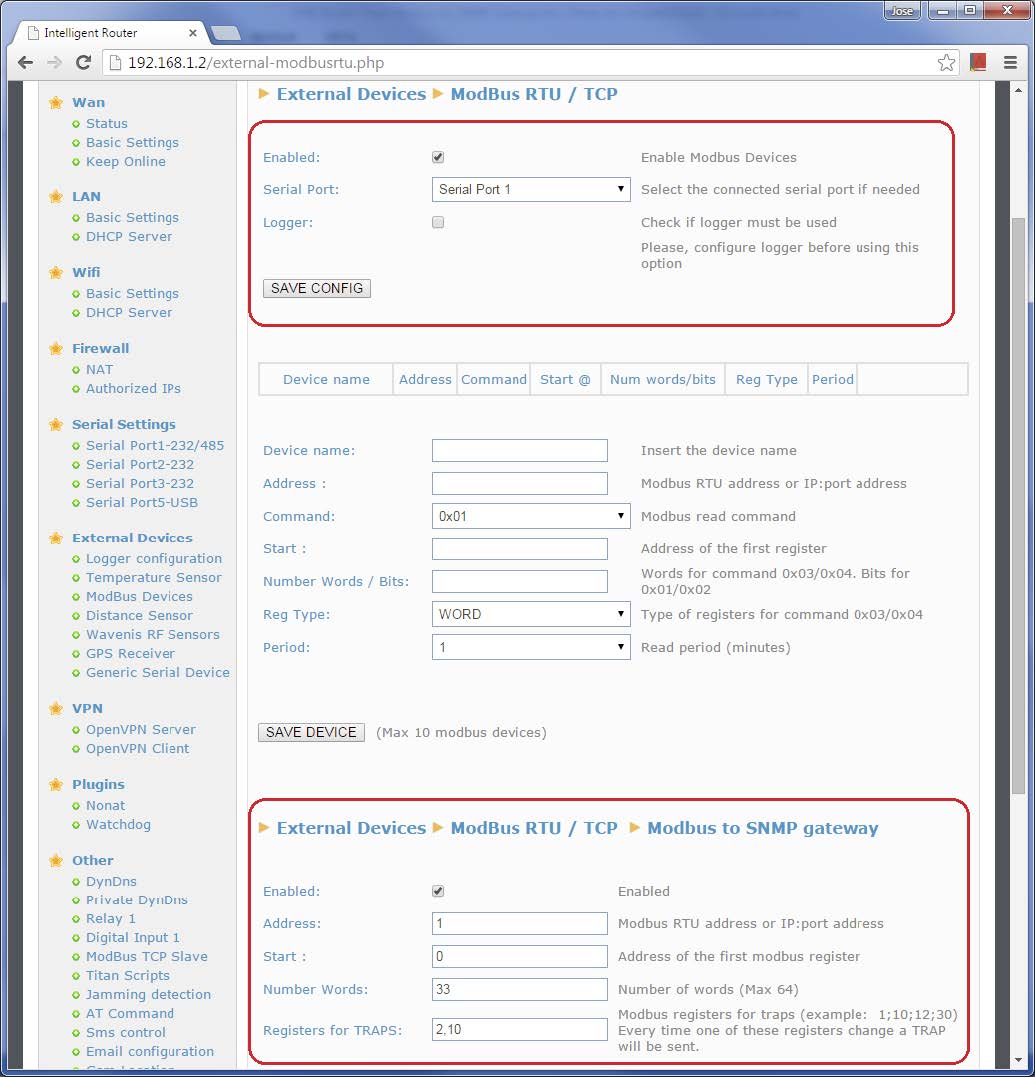
The Modbus-SNMP gateway is configured in the lower part of this screen. We must select “Enabled” and indicate the Modbus device’s address to be used (in this example, @1). We must also specify the first register (in this example, @0) and the number of registers to be read (in this example, 33), as well as those registers for which the Titan router will not send a notification TRAP in the event of changes in status (in this example, 2 and 10). Note that this must be specified using commas to separate each number, without spaces. The configured registers will be read by the Titan router every 5 seconds, using the Modbus command 0x03. Only registers of the type “word” will be read.

Note that the maximum number of registers to be mapped between the Modbus RTU and SNMP is 500. A list of the existing relations between the 500 Modbus registers and the OIDs and TRAPS is included in the MIB database. It is not necessary for the 500 registers to be read consecutively. For example, if you only wish to read registers 1 to 5 and 100 to 200, this can be specified in the “Number Words” field as follows: “1-5;100-200”.

Once configured, the device must be reset for this configuration to be effective.

Checking the Configuration

There are several ways in which the configuration can be checked. The most obvious is to use real devices. However, an alternative method is to use emulators, given that this provides the possibility to detect and resolve problems that could occur. We will use the latter in this section.

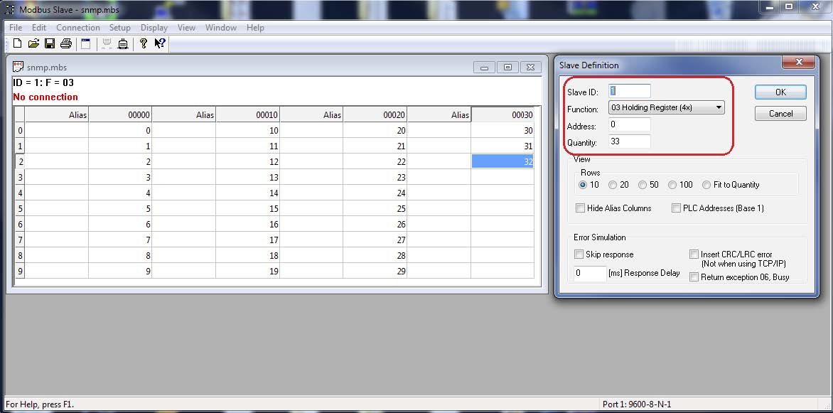
Firstly, we must connect the Titan router’s serial port to the RS232 port in our PC. Then, we will use a piece of PC software called “Modbus Slave” to act as our Modbus device to be read. A slave device will be created with address @1, 03 reading function, first register as 0 and the number of registers to be 33.

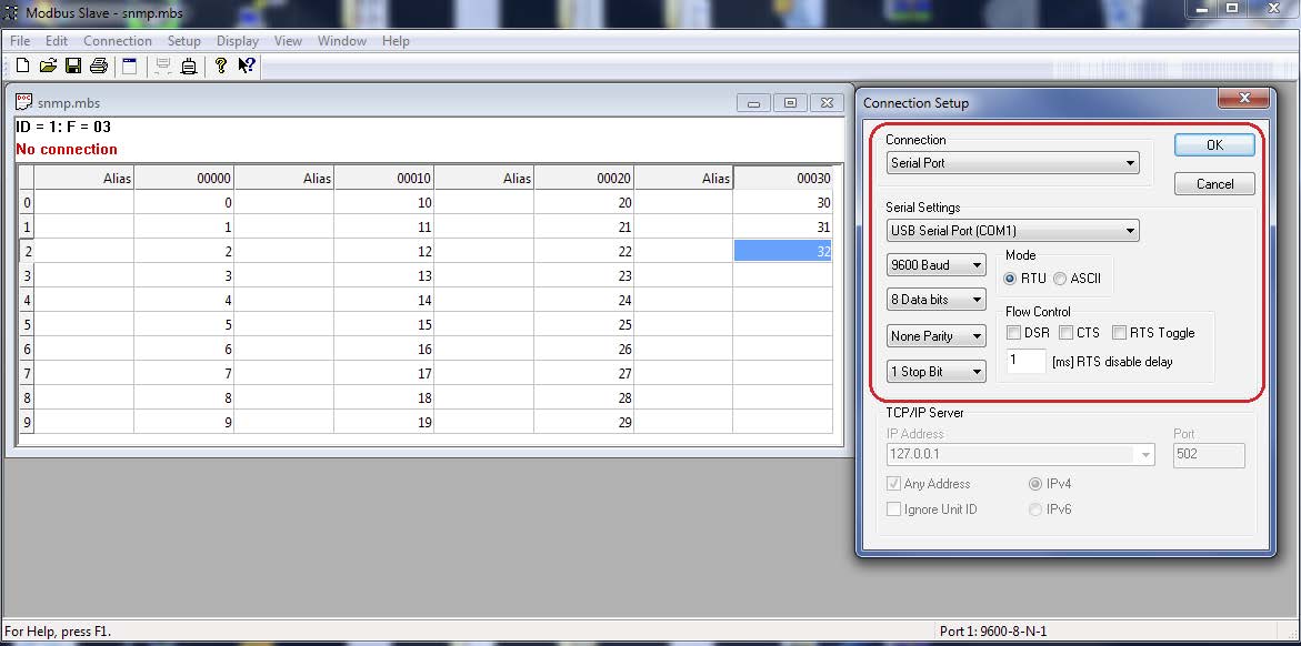
The PC’s serial port will be configured using the same speed as the real device (9600,8,N,1).

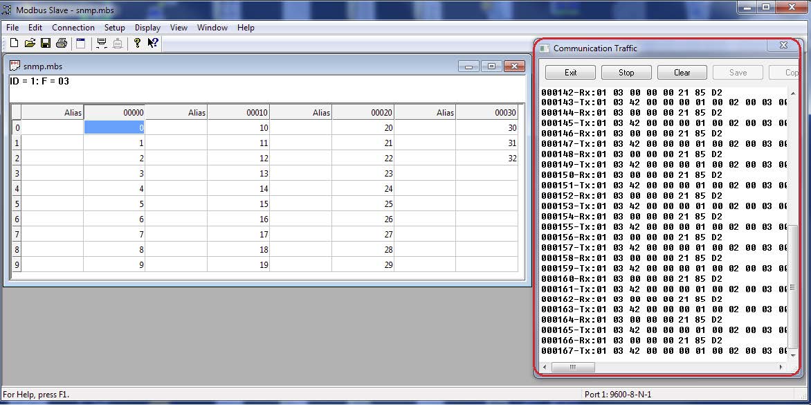
Upon pressing OK and establishing a connection, we will go to the menu “Display > Communication” where we must activate the visor for the communication traffic between the Titan router and the emulator.

Providing everything is correct, we should see RX strings which are the ‘questions’ sent to the emulator by the Titan router. The TX strings are the responses received by the Titan router.

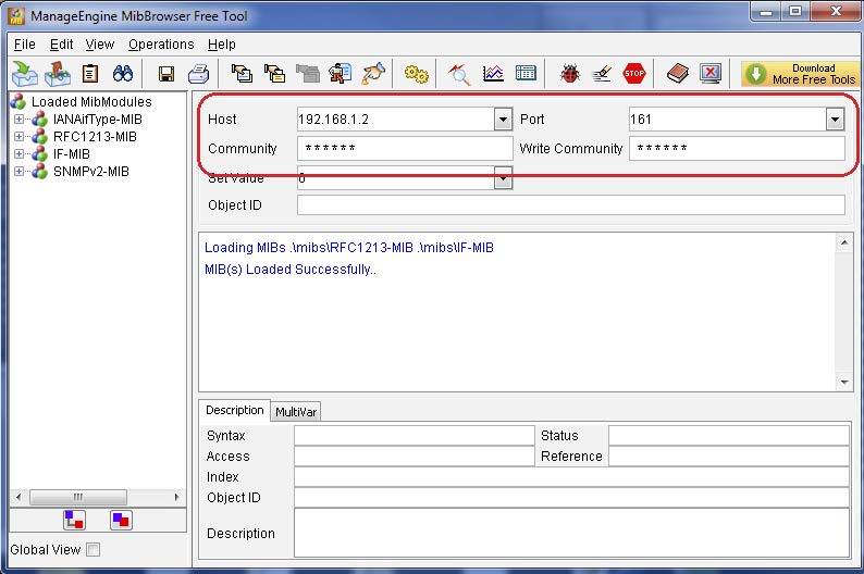
If everything is correct (i.e. communications between the Modbus registers and the emulator are working correctly), we can continue to the SNMP section. For this we will use MIB Browser software. In this example, we have used “ManageEngine MibBrowser5”, which is free. Here we must configure the local Internet IP address (the default value is 192.168.1.2), as well as specifying the UDP port as 161, and inserting “public” into the community fields.

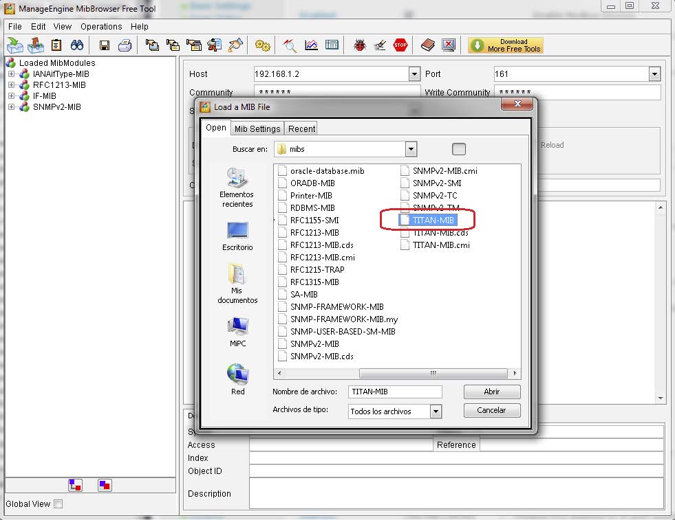
After completing this, the MIB file from the Titan device must be copied to the “mibs” folder, which should be located where the “ManageEngina MibBrowser” was installed (usually this would be “C: Program Files (x86)Manage EngineMibBrowser Free Toolmibs”. The MIB file can be downloaded using the Titan router as explained in section 3 of this Application Note. Once copied, it can be loaded using the menu “File > Load MIB”. We will choose the file TITAN-MIB.

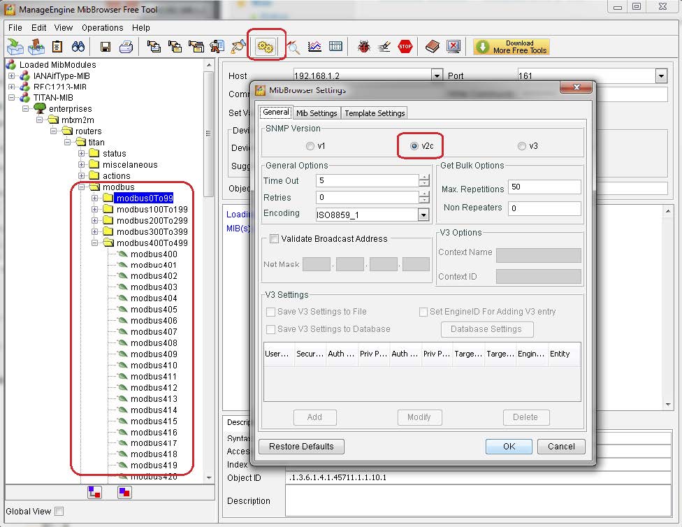
We can see that the TITAN-MIB device now appears in the menu to the left of the screen, as well as the different OIDs. In particular, we are interested in the OIDs “modbus0” to “modbus32”. The last thing to be configured at this stage is the SNMP version to be used, in this case v2c.

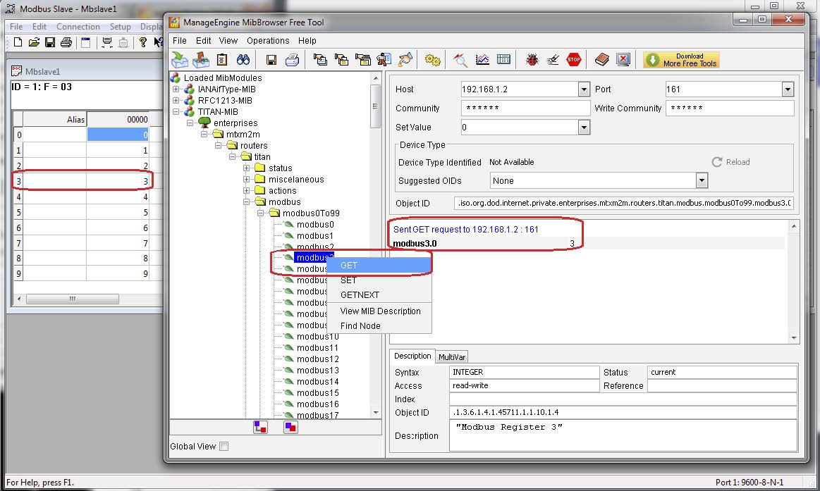
Once completed, we can carry out SNMP readings, observing how these affect the Modbus registers contained in our emulator. For example, by right clicking on OID Modbus 3, we can carry out a “GET” function. The result of this action is shown to the right of the screen (the value 3), which corresponds to the value contained in the Modbus 3 register of our emulator.

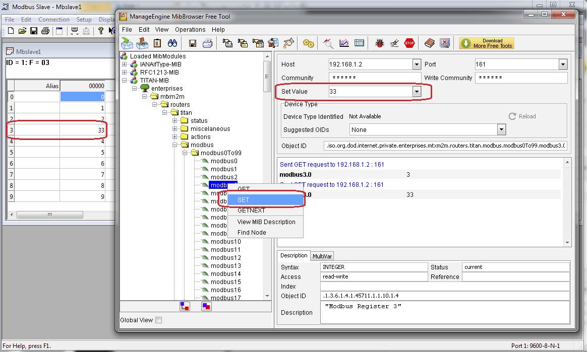
To test a SET SNMP command, for example, inserting the value 33 in the same OID, we must write this value in the field “Set Value” and once again right click the OID, selecting the SET command. This change will be visible in the corresponding register of our emulator.

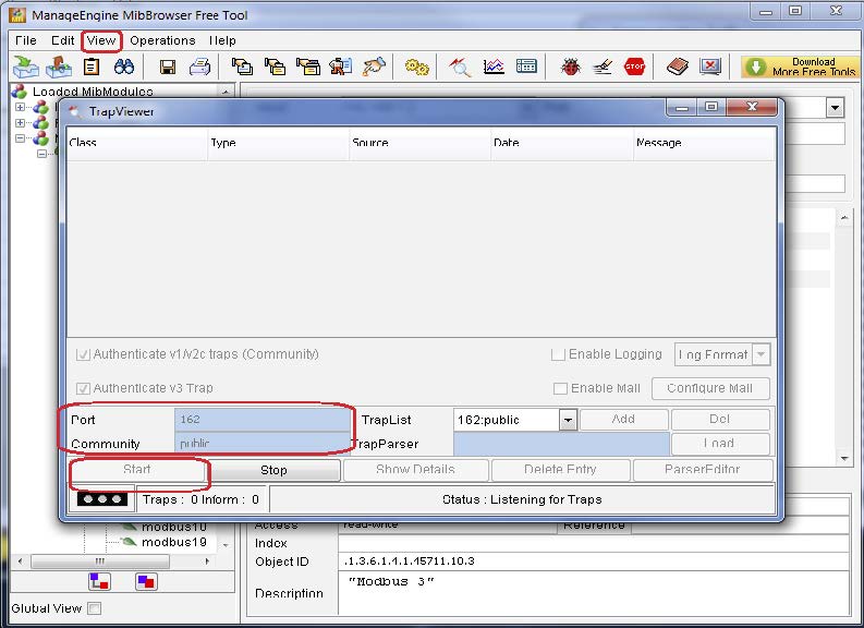
Now we must check the TRAPS. In Section 4 of this Application Note we saw that a TRAP must be sent in the event of any changings in the values contained in the Modbus registers 2 and 10. To see the TRAPS, we must go to the menu “View > Trap Viewer”, specifying the field “Port 162”, as well as inserting the value “public” into the Community field. To finish, we must click “Start”.

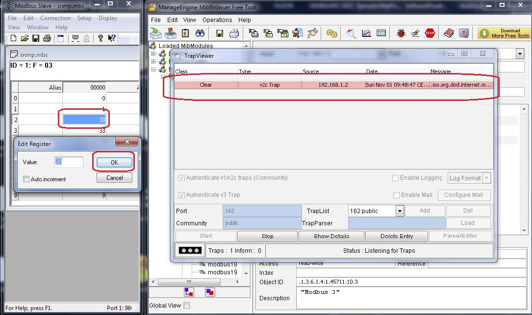
Now, by double clicking the Modbus 2 register in our emulator and changing the value of the register to 20 for example, we will see that a new TRAP will appear in the screen, indicating that a change in this register has occurred.

FAQs

  • In this Application Note, the process explained is for a Modbus RTU device. Is the process the same for a Modbus TCP device?
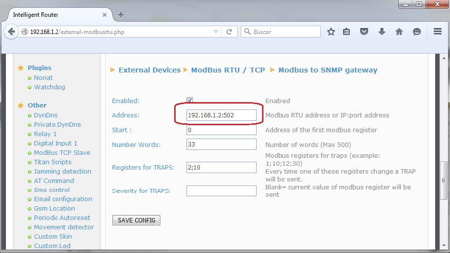
    Yes, it is. We would have to change the Modbus address value for the IP address. For example, in this example we specified the value “1” in the Modbus RTU device’s address. We would change this to “192.168.1.100:502” (assuming the IP address were 192.168.1.100 and the TCP port awaiting responses were 502). The following screen shows this change.

  • This example sends a TRAP when a register changes value, which is useful for those Modbus registers linked to some type of alarm. Would it be possible for TRAPS to be sent when the value of a register is greater than a certain value?
    Yes, it would. However, the configuration for this scenario is slightly more complex. The configuration would have to be done from the menu “Titan Scripts”. For example, let us
    assume that we want the following to occur:
    1. When the Modbus 10 register (of the Modbus RTU device with address @1) **********, a TRAP must be sent by the Titan router with severity “1” ([.1.3.6.1.4.1.45711.12.1.1)
    2. When the sum of the Modbus 10 and 11 registers (of the Modbus RTU device with address @1) is 50, a TRAP must be sent by the Titan router with severity “2” [.1.3.6.1.4.1.45711.14.1.1)
    3. When the Modbus 12 register (of the Modbus RTU device with address @1) is greater than 50, an SMS must be sent by the Titan router to the cell phone number +34123456 with the text “Temperature Alarm”. (For this option, a SIM card must be inserted in the Titan router)

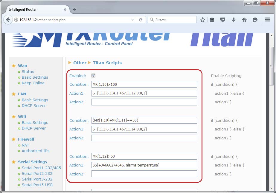
These three options can be specified in the menu “Other > Titan Scripts”, using the ST (Send Trap) and SS (Send SMS) commands.

  • In this example, 33 consecutive Modbus registers are read. How would non-consecutive registers be read (for example, register 200, 210, and the intervals 400-410 and 430-600)?
    This is possible. By default, the register “Number Words” indicates the number of registers to be read from the register identified in “Start”, but it is possible to enter intervals in this field. In order to read the registers as given in the example, we would need to configure the Titan router as shown in the following screen:

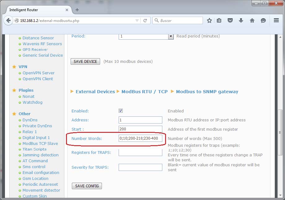
Here, we indicate in the “Start” field register number 200. Then, in the “Number Words” field we would enter “0” (200+0=200), “10” (200+10=210), and the intervals “200-210” and “230-400”. Each register/interval is separated by a semi-colon.

  • I need my PLC Modbus TCP device to have SNMP connectivity, as per the example given in this Application Note; however, I do not want the Titan router to send the TRAPS, yet the PLC. Is this possible?
    Yes, it is. The Titan router works like a Modbus TCP master, periodically reading the Modbus registers from the PLC, but it can also work simultaneously as a Modbus TCP slave. When the Titan router is in TCP Slave mode, AT commands can be sent via Modbus, through which SMS messages, emails and TRAPS can be sent, as well as the possibility of switching relays or consulting network coverage.
    For more information regarding how to use AT commands with Modbus TCP, please consult Application Note 10 (AN10-Sending SMSs, EMAILs, TRAPS SNMP using Modbus TCP).

Do you have a question? Need a quote? Please contact us.

  • This field is for validation purposes and should be left unchanged.

Appendices and other documents

Annexes et autres documents

Appendices and other documents

Appendices and other documents

Appendices and other documents

Appendices and other documents

Appendices and other documents

Appendices and other documents

Appendices and other documents

FAQ

No, the concentrator is not able to decrypt data from WM-BUS equipment because it does not have a safe on board to guarantee the security of the encryption keys of your equipment. The recovered data is deposited without modification (without decryption) by the concentrator on your remote server.
Please check these items in this order:
  • the battery level: if the battery level is too low or empty, the product will not run properly or not run at all.
  • Modem reception level: a bad signal at the modem may also prevent the hub from uploading files. Look to move the product or install an external antenna to improve signal quality.
  • The last configuration file: a bad configuration file can block the product.

Remotely, by checking the regularly uploaded files if the product configuration is correct.

On site, by passing the magnet over the product, you will hear 3 short beeps.

Replace the product and inject the configuration from the old product into the new one. If a white list is used, remember to inject it into the new product as well.

Appendices and other documents

Other manuals

Application Notes

FAQ

Gateway configuration:

Start by checking that the computer’s IP parameters are compatible with the WebdynSunPM IP address (by default 192.168.1.12)

Launch a web browser (Chrome, Firefox, Edge, Safari, etc.) and enter the WebdynSunPM concentrator IP address in the address bar. An authentication page is displayed:

The default accesses are:

IdentifiantMot de passe
userhighhigh

Click “Login”

There are two configuration solutions, using the web interface and using text messages:
  • Configuration using the web interface:
Start by establishing a connection to the concentrator by connecting to it to access the server configuration: Enter the “ethernet” or “modem” connection type: For an ethernet configuration, make sure the IP parameters are compatible with server access according to the concentrator local network configuration. For an ethernet connection, the configuration must be compatible with the concentrator’s local network topology so that it can access the servers. This configuration is done from the “Networks” configuration page (see section 3.2.2.3: “Networks). For a modem connection, the modem configuration must be correct before a connection can be set up. This configuration is done from the “Modem” configuration page (see section 3.2.2.4: “Modem). The parameters for the servers to be configured are at least the following: Therefore the following fields need to be configured: “Interface”, “Type”, “Server type”, “Address”, “Port”, “Login” and “Password”. The other fields can be left at the default values subject to the directories having been properly created beforehand. See section 3.1.2: “Configuration files for more details.
  • Text message configuration:
Text message configuration requires sending the following commands:
      • Apn: to configure the SIM card APN. (see section 3.2:“apn” modem configuration command)
      • Ftp: to configure the FTP server that will contain the concentration configuration (see section 3.3: “ftp” FTP configuration command”).
      • Connect: to launch the connection to the FTP server and load the configuration (see section 3.1: ““connect” connection command

Access to the FTP server depends on the selected solution.

If you have chosen a portal, it will give you the FTP server access identifiers.

If you want to use your own FTP server, contact your network administrator.

For all other configurations, and to determine the best solution, contact the Webdyn sales department which will advise you and direct you to the relevant contacts: contact@webdyn.com

General gateway use

There are 2 methods to force a concentrator factory reset:
  • Press the Factory Reset button on the concentrator for 20 seconds:
Wait. The concentrator will reboot using its factory configuration.
  • If a SIM card is installed and configured, a “factory” text message can also be used for factory reset. Just send the “factory” text message to the SIM card phone number (see section 3.7: “factory” reset command”)

It is possible to send commands to connected devices if they accept them.

The WebdynSunPM can store up to 50Mb of uncompressed data per declared device.

If there is no access to the remote server, the WebdynSunPM concentrator can store the data for several months.

The maximum data storage time varies depending on the amount of data to be collected and the configured collection frequency.

The average storage time varies from 3 to 4 months.

The average service life of the battery is 5 years.

It may vary depending on the installation environment.

All our products are guaranteed for 2 years.

For more information, read the general terms and conditions of sale.

The data volume depends on the exchanged files.

The average is about 5 MB per month but this varies from one installation to another.

Inverter compatibility

See section 1.4: “Supported devices”.

Modbus device compatibility:

Yes, different Modbus devices can be connected to the same serial port.

Device compatibility:

    • Same type of RS485 or 4 wire connection.
    • All devices should be able to be configured using identical bus specifications. Same speed, same parity, same number of stop bits and data bits on all devices and on the WebdynSunPM.
    • Each device must be assigned a unique Modbus address (between 1 and 247) on the bus. (UnitID)

Appendices and other documents

FAQ

CONFIGURATION OF THE WEBDYNSUN GATEWAY

  • Start by checking that your computer’s IP parameters are compatible with the WebdynSun’s “IP” address (the default is 192.168.1.12). 
  • Next, launch a web browser (Firefox or IE) and enter the WebdynSun’s IP address in the address bar. An authentication page will appear: 

The default accesses are:
Username: userhigh
Password: high

  • Click on “log in”  

There are two types of configuration: via the web interface or via SMS.

Configuration of the web interface:

1/ Go to the configuration page with the gateway IP address (default 192.168.1.12)

2/ Go to the Configuration tab.

3/ Select either the Ethernet or modem connection mode:

If connecting via the local network (Ethernet):

  • Edit the WebdynSun’s IP parameters by assigning it a network-compatible address.

Please note, all fields must be completed in accordance with the configuration of your local network.

If connecting via the GPRS network (Modem):

  • Change the connection settings of the GPRS modem to the settings provided by your mobile operator.

4/ Edit the FTP server parameters.

5/ Confirm the changes.

6/ Restart the WebdynSun gateway using the new settings.

7/ In the menu, click on the “installation” tab, followed by the “connection” sub-tab and start the connection.

Configuration via SMS:

This configuration method requires the use of an active SIM card with a data option and a pin code that must be either “0000” or disabled.
The SIM card must be inserted into the unit before connection to the mains supply.
After connection to the mains supply, send the following SMS messages to the number of the previously inserted SIM card:

SMS for configuring the APN:
After replacing the generic fields with those of your operator, send the following SMS*:
apn=apn_name;usr=user_name;pwd=password;

Replace the above SMS fields with the following information:

  • apn_name: APN name supplied by your mobile operator
  • user_name: APN ID supplied by your mobile operator
  • password: APN password supplied by your mobile operator

SMS for FTP configuration:
After replacing the generic fields with those of your FTP server, send the following SMS*:
Ftp=server_name:user_name:password:port;

Replace the above SMS fields with the following information:

  • server_name: FTP server address
  • user_name: FTP account ID
  • Password: FTP account password
  • Port: FTP server port (the default port is 21)

Connection SMS:

Send the word “connect” by SMS* to launch a connection to the FTP server

*Please note: the formatting of the SMS must be exactly identical to that shown above (e.g.: no spaces between characters, etc.)

There are 2 ways of resetting the gateway.

  • If connecting by Ethernet:
    • Disconnect from the mains
    • Remove the cover
    • Disconnect the battery
    • Put the DIP Switch 2 on the WebdynSun card in “ON” position
    • Start the WebdynSun by connecting it only to the mains power supply
    • Wait until all the LEDs flash and then stop flashing (3 to 5 mins).
    • Disconnect from the mains
    • Reset the Dip Switch 2 to “OFF” 
    • Reconnect the battery
    • Reconnect to the mains supply and the WebdynSun starts normally.
  • If there is a SIM card inserted in the unit:
    • Send an SMS message containing the word “factory” to the number of the inserted SIM card.

NB : Resetting the gateway restores the configuration to its original state. Please note: data will be saved but the specific settings will not. Therefore, all the settings must be reconfigured.

Commands can be sent to connected devices with the exception of certain inverters and Modbus slaves that do not accept write requests.

If the device allows it, command files can be created on the FTP server.

The WebdynSun has a memory of about 100MB.

Therefore, if the remote server cannot be accessed, the WebdynSun gateway can backup data for several months.
The maximum data backup time varies depending on the amount of data to be collected.

The average backup time ranges from 3 to 4 months.

The average battery life is 5 years.

It may vary depending on the installation environment.

Yes, data may be sent to a PLC if the latter is equipped with a Modbus protocol.
The “Report” configuration file allows the WebdynSun gateway to automatically write the values read on a Modbus slave

All our products are guaranteed for 2 years.

For further information, please see our general conditions of sale.

Files uploaded by the WebdynSun gateway are compressed in Gz format.

The data contained in these files is structured in csv format.

The data volume depends on the files exchanged.

The average is about 5 MB per month but this varies from one installation to another.

INVERTER COMPATIBILITY WITH THE WEBDYNSUN GATEWAY

Different brands of inverter may be connected to the RS485(B) port or via the Ethernet port if the inverter protocol is based on the Modbus protocol (RTU or TCP).

However, different brands of inverters cannot be connected to the same RS485(A) port.

For a list of compatible inverters, please see the product page of the WebdynSun data gateway
  • Check if the correct inverter protocol is selected before starting detection:
  • Check the wiring and configuration of the inverters by referring to the inverter appendices.
  • Check that the inverters are not in OFF or stand-by mode.
  • Check that the line end plugs on the RS 485(A) Bus are turned on.

COMPATIBILITY WITH MODBUS DEVICES

Yes, any device you wish to connect must be configured and its Modbus definition file must be created.

The configuration is mainly based on the RS485 serial bus parameters and the IP parameters.

Yes, different Modbus devices can be connected to the same RS485 (B) port.

However, they must have the same communication parameters (bus parameters or compatible IP parameters), in order for them to communicate with each other.

Appendices and other documents

Appendices and other documents

Appendices and other documents

Appendices and other documents

Appendices and other documents

  • Warning – Firmware update V4.07.02 For the old version with SIM CARD of the pin code is 0000 you can update in this version. For the second case : When you insert a SIM CARD with pin code is 0000 used in this version (4.07.02) Downgrading to a previous version is not permitted.

Appendices and other documents

  • Warning – Firmware update V4.07.02 – For the old version with SIM CARD of the pin code is 0000 you can update in this version.

    For the second case : When you insert a SIM CARD with pin code is 0000 used in this version (4.07.02) Downgrading to a previous version is not permitted.

Annexes and other documents

FAQ

Annexes and other documents

FAQ

Annexes and other documents

FAQ

Annexes and other documents

FAQ

CONFIGURATION OF THE WEBDYNRF GATEWAY

  • If the file is deleted from the directory after connecting the WebdynRF gateway, the problem is usually due to a file format error. The configuration and control files must follow the format described in the schema (XSD) files. To check schema consistency, open the XML file with the Notepad++ text editor and install the “XML Tool” add-on. Next, copy the corresponding XSD file to the XML file in the same directory, and select “Validate now” in XML Tool. Errors detected by the tool should be displayed.
  • If the file is not deleted from the server, the most common problem is that the file has not been located correctly. The file must be available on the server in the “INBOX” directory and in the sub-directory bearing the product UID name (e.g.: “/INBOX/0045CE/”).

GENERAL USE OF THE WEBDYNRF GATEWAY

The amount of data exchanged on the GPRS network varies depending on the configuration. However, the average consumption would be about 5MB / month.
The WebdynRF gateway consumes an average of about 250mA.

There are 2 firmware updating methods:
Local updating:
On the WebdynRF configuration interface, go to the “Actions” tab and select the updater in the “File upload” menu before clicking on the “Upload” button

Remote updating:
Upload the file containing the updater (file with extension “.bz2”) in the “BIN” directory to the FTP server . Next, place the update command in the INBOX directory corresponding to your gateway (“INBOX/”, with, the identifier of the gateway concerned)

The update command must follow the following format:

      updater.tar.bz2
      checksum_md5

updater.tar.bz2
checksum_md5

With:

  • updater.tar.bz2: Updater file name uploaded to the “BIN” directory
  • checksum_md5: Md5 code of the updater file

A lack of connection to the FTP server may be due to a network connection problem (Ethernet or GPRS), an FTP login problem or a failure to initiate the connection.

If you cannot connect to the network, check the following points:

  • Ethernet:
    • Modem set to “off” or “always off”
    • “Gateway” fields correctly entered
    • At least one DNS server must be configured
  • GPRS:
    • Modem set to “on”
    • APN, APN ID and APN password correctly entered
    • GPRS call number set to “*99***1#”

If you cannot log in, check the following points:

  • Incorrect FTP parameters
  • TCP port 21 closed at output
  • Domain name resolution problem: the DNS server is not specified

If the connection fails to initiate:

In this case, only the automatic connection does not work. The problem is probably caused by an incorrect schedule configuration. Please note, the schedule ID must be an integer.

 PARTICULAR APPLICATION OF THE WEBDYNRF WIRELESS M-BUS GATEWAY

For the WM-bus module data to be transmitted, you must:

  • Choose the mode corresponding to the modules used (S, T or N)
  • Define the modules or groups of modules to be processed

A module may be defined in a unique way by all the fields below:

  • Id
  • Manufacturer
  • Version
  • Medium

If a module’s data is encrypted, the encryption key for this module can be defined in the “Key” field.

To simplify the entry of the modules to be processed, a module group can be defined that conforms to the fields entered. The other fields will then be left empty (below is an example of a configuration for retrieving all Webdyn manufacturer (WDN) modules with the encryption key “00000000000000000000000000000000”.

  •   Id :
  •   Manufacturer : WDN
  •   Medium :
  •   Version :
  •   Label : Webdyn
  •   Key : 00000000000000000000000000000000

Note: In order for the modules (filters) entered to be taken into account, the “ByPass filter” mode must be deactivated.

Click here to read the media file 

Click here to read the units file 

 PARTICULAR APPLICATION OF THE WEBDYNRF WAVENIS

The tool is connected to the gateway via the installer access (install).

It is therefore necessary to use the installer password (default is “middle”), and not the administrator’s password (default is “high”)

The statuses transmitted by the WebdynRF gateway are the raw values contained in the Wavenis modules. They are transmitted without interpretation. For further details, please refer to the Coronis module manuals.

Appendix and other documents

FAQ

CONFIGURATION OF THE WEBDYNRF GATEWAY

  • If the file is deleted from the directory after connecting the WebdynRF gateway, the problem is usually due to a file format error. The configuration and control files must follow the format described in the schema (XSD) files. To check schema consistency, open the XML file with the Notepad++ text editor and install the “XML Tool” add-on. Next, copy the corresponding XSD file to the XML file in the same directory, and select “Validate now” in XML Tool. Errors detected by the tool should be displayed.
  • If the file is not deleted from the server, the most common problem is that the file has not been located correctly. The file must be available on the server in the “INBOX” directory and in the sub-directory bearing the product UID name (e.g.: “/INBOX/0045CE/”).

GENERAL USE OF THE WEBDYNRF GATEWAY

The amount of data exchanged on the GPRS network varies depending on the configuration. However, the average consumption would be about 5MB / month.
The WebdynRF gateway consumes an average of about 250mA.

There are 2 firmware updating methods:
Local updating:
On the WebdynRF configuration interface, go to the “Actions” tab and select the updater in the “File upload” menu before clicking on the “Upload” button

Remote updating:
Upload the file containing the updater (file with extension “.bz2”) in the “BIN” directory to the FTP server . Next, place the update command in the INBOX directory corresponding to your gateway (“INBOX/”, with, the identifier of the gateway concerned)

The update command must follow the following format:

      updater.tar.bz2
      checksum_md5

updater.tar.bz2
checksum_md5

With:

  • updater.tar.bz2: Updater file name uploaded to the “BIN” directory
  • checksum_md5: Md5 code of the updater file

A lack of connection to the FTP server may be due to a network connection problem (Ethernet or GPRS), an FTP login problem or a failure to initiate the connection.

If you cannot connect to the network, check the following points:

  • Ethernet:
    • Modem set to “off” or “always off”
    • “Gateway” fields correctly entered
    • At least one DNS server must be configured
  • GPRS:
    • Modem set to “on”
    • APN, APN ID and APN password correctly entered
    • GPRS call number set to “*99***1#”

If you cannot log in, check the following points:

  • Incorrect FTP parameters
  • TCP port 21 closed at output
  • Domain name resolution problem: the DNS server is not specified

If the connection fails to initiate:

In this case, only the automatic connection does not work. The problem is probably caused by an incorrect schedule configuration. Please note, the schedule ID must be an integer.

 PARTICULAR APPLICATION OF THE WEBDYNRF WIRELESS M-BUS GATEWAY

For the WM-bus module data to be transmitted, you must:

  • Choose the mode corresponding to the modules used (S, T or N)
  • Define the modules or groups of modules to be processed

A module may be defined in a unique way by all the fields below:

  • Id
  • Manufacturer
  • Version
  • Medium

If a module’s data is encrypted, the encryption key for this module can be defined in the “Key” field.

To simplify the entry of the modules to be processed, a module group can be defined that conforms to the fields entered. The other fields will then be left empty (below is an example of a configuration for retrieving all Webdyn manufacturer (WDN) modules with the encryption key “00000000000000000000000000000000”.

  •   Id :
  •   Manufacturer : WDN
  •   Medium :
  •   Version :
  •   Label : Webdyn
  •   Key : 00000000000000000000000000000000

Note: In order for the modules (filters) entered to be taken into account, the “ByPass filter” mode must be deactivated.

Click here to read the media file 

Click here to read the units file 

 PARTICULAR APPLICATION OF THE WEBDYNRF WAVENIS

The tool is connected to the gateway via the installer access (install).

It is therefore necessary to use the installer password (default is “middle”), and not the administrator’s password (default is “high”)

The statuses transmitted by the WebdynRF gateway are the raw values contained in the Wavenis modules. They are transmitted without interpretation. For further details, please refer to the Coronis module manuals.

Annexes et autres documents

  • WARNING :  Pour les anciens produits qui disposent d’une carte SIM avec un code PIN à 0000 , la mise à jour vers la version 4.07.02 sera fonctionelle.

    Second cas : Si la carte SIM avec un code PIN à 0000 est utilisée dans cette version (4.07.02), le passage vers une mise à jour antérieure est interdit.