Looking for something else?
Most MTX modems have one or more analog inputs (0-50V or 4-20mA). The ADC_ parameters allow you to configure the behavior of these analog inputs. For example, you can configure an analog input so that when it exceeds a level, it will send alarm SMS, or send an MQTT message, or make a voice call, or execute an AT command automatically (or a batch of AT commands) , etc.
We strongly recommend that you take a look at the examples in Annex 8 to better understand the operation.
Table of Contents
ADC_mode0, ADC_mode1, ADC_mode2
Description: The ADCs of the MTX modems (analog inputs) can be of various types depending on the model of the modem used. They can be voltage type (0-50V) or current type (4-20mA).
This parameter indicates to the modem how each analog input will be used. See the characteristics tables in Annex A of this manual to find out the possibilities of each ADC depending on the MTX modem model.
Remember that to configure an analog input as voltage or current, in addition to indicating it in this parameter, you must appropriately configure the modem microswitches (see Annex A).
Possible values:
- voltage, current
- Default values: voltage
Aditional notes:
- Set the parameter value as “voltage” if the ADCx wants to be used as voltage input (0-50V). Remember to also configure the modem microswitches for this purpose
- Set the parameter value to “current” if the ADCx wants to be used as current input (0-20mA). Remember to also configure the modem microswitches for this purpose
ADC_config0, ADC_config1, ADC_config2
Description: Using these parameters, you can configure the behavior of each of the modem’s ADC inputs (analog inputs).
- Default values: normal
- normal
With this value the ADC input is simply configured as an analog input without any special behavior assigned. This value is useful, for example, when you want to simply query the value of an analog input (for example with the command AT ^ MTXTUNNEL = GETIOS, or with the periodic datalogger, etc.).
Example:
ADC_mode0: voltage
ADC_config3: normal
This example configures ADC0 as a normal voltage input.
- sms;<minValue>;<maxValue>;<hist>;<timeout>;<messageMin>;<messageMax>;<messageNormal>
With this value the ADC input is configured to send an SMS alarm based on the ADC value.
sms: text indicating that the ADC is associated with an SMS alarm
<minValue>: 0 … 50000. When the ADC value is equal to or less than this value, an SMS alarm will be generated with the text <messageMin>
<maxValue>: 0 … 50000.
When the ADC value is equal to or greater than this value, an SMS alarm will be generated with the text <messageMax>
<hist>: 0 … 50000 hysteresis
<timeout>: 0 … 3600
In the event of an SMS alarm condition, this value indicates the maximum time between shipments. This prevents continuous SMS sending if an analog input changes state continuously by accident.
<messageMin>: max. 160 characters (without ; )
In the event of a low value SMS alarm condition, this is the text of the SMS message to be sent.
<messageMax>: max. 160 characters (without ; )
In the event of a high value SMS alarm condition, this is the text of the SMS message to be sent.
<messageNormal>: max. 160 characters (without ; )
In the event that the ADC value returns to a normal state after an alarm state, this is the text of the SMS message to be sent.
Example:
ADC_mode0: voltage
ADC_config0: sms;2000;8000;100;60;Alarm ADC0 Low;Alarm ADC0 High;Alarm ADC0 normal
NOTE: This example configures the ADC0 as a voltage input and will send an SMS message whenever the value is below 2000mV or above 8000mV, with a hysteresis of 100mV and a timeout of 60 seconds.
NOTE 2: The recipient’s phone numbers are configured in the ALARM_smsNumberX parameters.
- at;<minValue>;<maxValue>;<hist>;<atMin>;<atMax>;<atNormal>
With this value the ADC input is configured to send an SMS alarm based on the ADC value.
at: text indicating that the ADC is associated with the execution of an AT command
<minValue>: 0 … 50000. When the ADC value is equal to or less than this value, the <atMin> command will be executed
<maxValue>: 0 … 50000. When the ADC value is equal to or greater than this value, the <atMax> command will be executed
<hist>: 0 … 50000 hysteresis
<atMin>: in the event of a low value alarm condition, this is the AT command that will be executedá
<atMax>: in the event of a high value alarm condition, this is the AT command that will be executed
<atNormal>: in the event that the ADC value returns to a normal state after an alarm state, this is the AT command that will be executed
Example:
ADC_mode0: voltage
ADC_config0: at;2000;8000;0;AT^MTXTUNNEL=SETIO,8,1;AT^MTXTUNNEL= SETIO,8,0;AT
- mqtt;<changeValue>;<timeout>
With this value the ADC is configured to send an MQTT message when the ADC changes a value to <changeValue>.
mqtt: text indicating that the ADC is associated with sending MQTT messages
<changevalue>: 0 …. 50000. When the analog input increases or decreases the configured value, an MQTT message will be sent
<timeout>: 0 … 3600 (secs.)
In the event of an MQTT shipping condition, this value indicates the maximum time between shipments. This prevents continuous MQTT message sending if an analog input changes state continuously by accident.
Example:
ADC_mode0: voltage
ADC_config0: mqtt;100;0
This example configures ADC0 as the voltage input associated with sending MQTT messages. A message will be sent every time the ADC0 input changes its 100mV value, with no timeout between messages. See Example 8.11 for more information and to view the MQTT message delivery format.
MQTT messages will be sent to the MQTT topic indicated in the MQTT_defaultIOTopic parameter with the Qos specified in MQTT_defaultIOQos.
- call;<minValue>;<maxValue>;<hist>;<timeout>
With this value the ADC is configured to make a voice call (without audio) when the value of the ADC is below or above thresholds.
call: text indicating that the ADC input is associated with making a voice call
<minValue>: 0 … 50000. When the ADC value is equal to or less than this value, a voice call will be made
<maxValue>: 0 … 50000. When the ADC value is equal to or greater than this value, a voice call will be made
<hist>: 0 … 50000 hysteresis
<timeout>: 0 … 3600 (secs.). Indicates the minimum time between 2 calls made by the modem
Example:
ADC_mode0: voltage
ADC_config0: call;2000;8000;100;300
This example configures the analog input ADC0 as associated with making a voice call. It will be carried out every time ADC0 has a value equal to or less than 2000mV or equal to or greater than 8000mV, with a hysteresis of 100mV and a timeout (minimum time between calls) of 300 seconds.
- wakeup;<minValue>;<maxValue>;<hist>
The wakeup mode indicates that the ADC will activate the 4G/3G/2G session for the configured time (in the GPRS_timeout parameter) when the analog value is pode below <minValue> or above <maxValue>.
call: text indicating that the GPIO, configured as input, is associated with the start of a 4G/3G/2G session
<minValue>: 0 … 50000 Cuando el valor del ADC valga igual o sea inferior a este valor, se activará la sesión 4G/3G/2G
<maxValue>: 0 … 50000. When the ADC value is equal to or greater than this value, the 4G/3G/2G session will be activated
<hist>: 0 … 50000 hysteresis
Example:
GPRS_timeout: 10
ADC_mode0: voltage
ADC_config0: wakeup;1000;9000;100
This example configures ADC0 as the analog voltage input associated with 4G/3G/2G session activation. When ADC0 <1000mV or ADC0> 9000mV the 4G/3G/2G session will be activated for 10 minutes. A 100mV hysteresis is configured.


 Enter the “ethernet” or “modem” connection type:
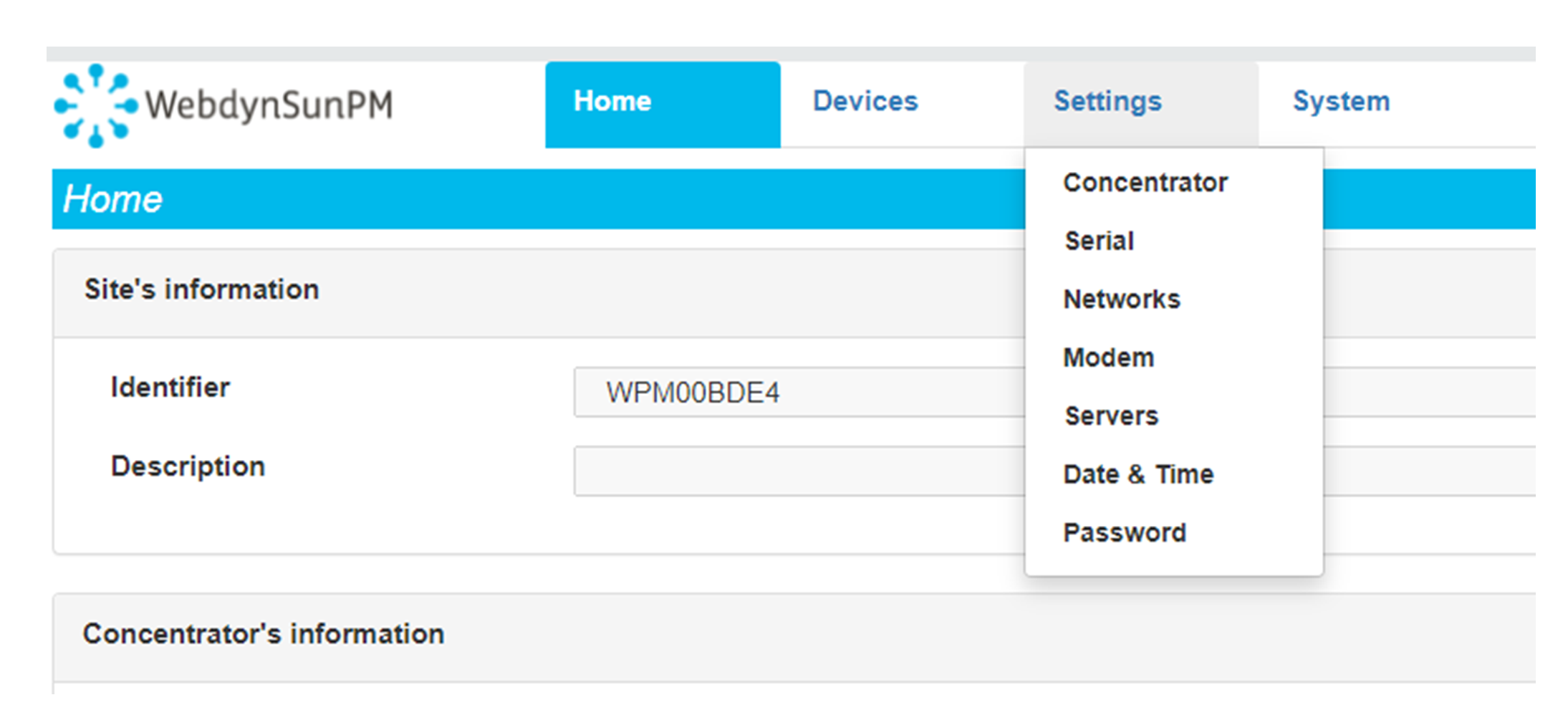
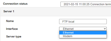 For an ethernet configuration, make sure the IP parameters are compatible with server access according to the concentrator local network configuration. For an ethernet connection, the configuration must be compatible with the concentrator’s local network topology so that it can access the servers. This configuration is done from the “Networks” configuration page (see section 3.2.2.3: “Networks”).
For a modem connection, the modem configuration must be correct before a connection can be set up. This configuration is done from the “Modem” configuration page (see section 3.2.2.4: “Modem”).
The parameters for the servers to be configured are at least the following:
 Therefore the following fields need to be configured: “Interface”, “Type”, “Server type”, “Address”, “Port”, “Login” and “Password”.
The other fields can be left at the default values subject to the directories having been properly created beforehand. See section 3.1.2: “Configuration files” for more details.


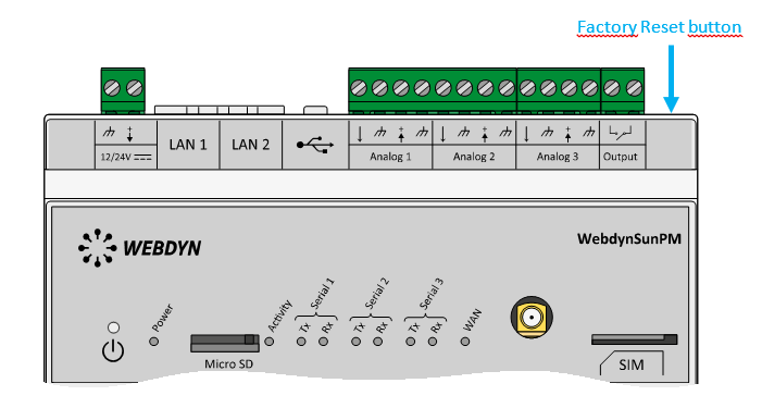 Wait. The concentrator will reboot using its factory configuration.

