Suchen Sie etwas anderes?
Table of Contents
Introduction
The MTX-Router EOS can be managed by sending SMS. This functionality allows the user to be able to carry out actions via SMS such as restarting, checking the coverage, connecting or disconnecting from the network or knowing the value of any router configuration parameter.
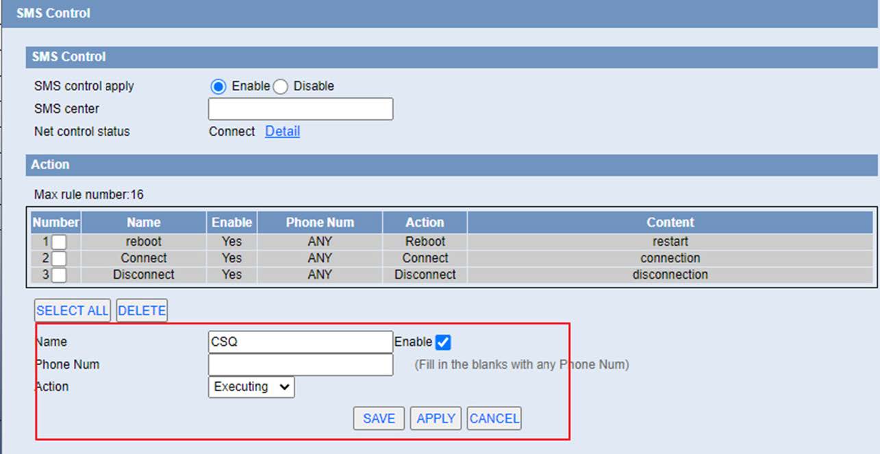
The SMS control configuration menu is found under “Serial and Remote Management”
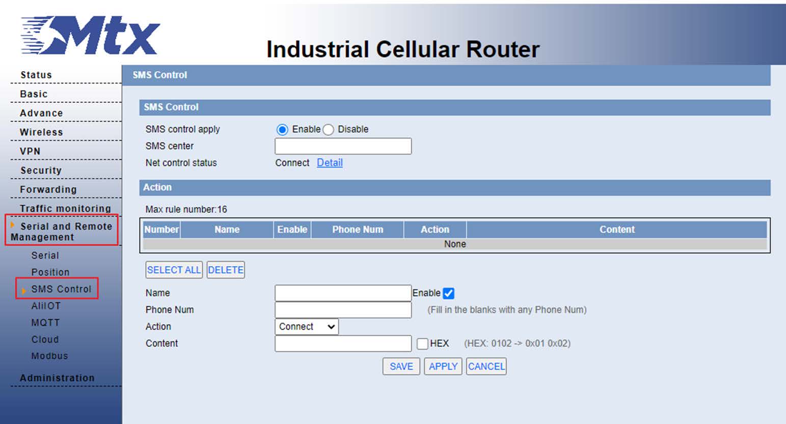
Here we can create up to 16 rules with the actions we want to do.
In the Name field, we will assign the name we want,
In the phone Number field, we will write the phone number from which we want to execute the action or we will leave it blank if we want it to be executed from any number.
In the Action field, we have 4 different types of actions:
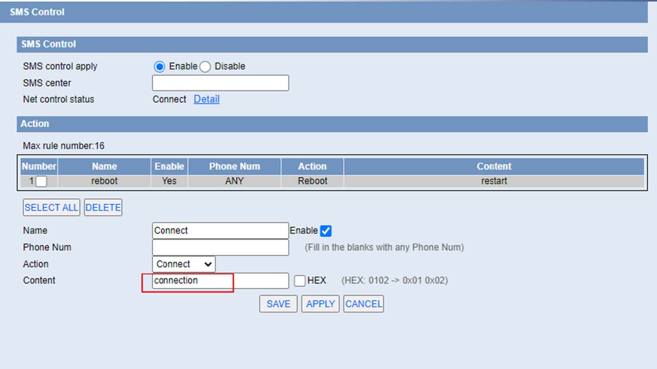
- Connect: For the router to connect to the data network
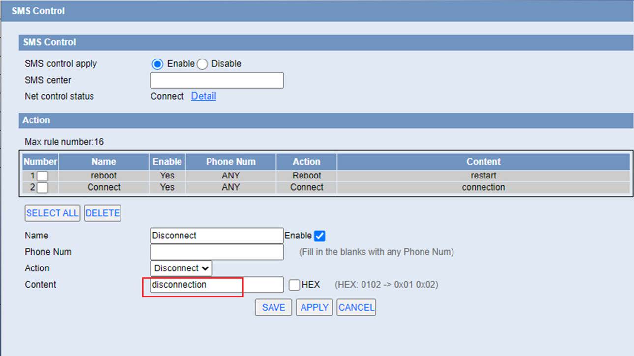
- Disconnect: For the router to disconnect from the data network
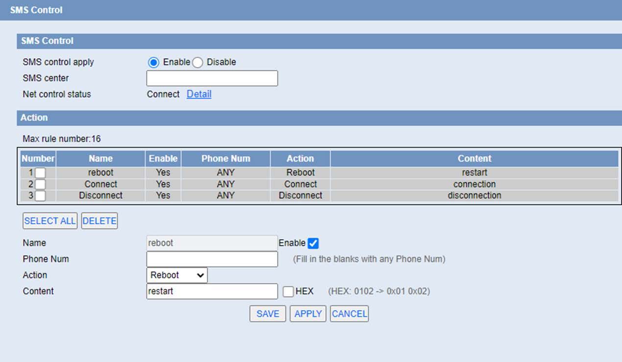
- Reboot: To reboot the router
- Executing: To execute some special request using the router’s nvram parameters
In the Content field, it will be the text that we will send in the SMS to execute each action
Some examples:
- Some examples of each action can be:

- Dissconnect: By sending the disconnection text the router will disconnect from the network:

- Reboot: By sending the text restart the router will restart:

- Executing: The text to be sent must follow the following format:
GETNVTMP=name1,name2,name3;
Where name1, name2, etc is the name of the nvram parameter. You can find the list of parameters at the end of the document in appendix 1. The CSQ command has also been implemented to see the signal quality:
Where when sending the command GETNVTMP = CSQ; , will return the current value of coverage:

Another example of this possibility would be
GETNVTMP=w1_wan_get_dns,csq,moimei,net_mode,simcops;
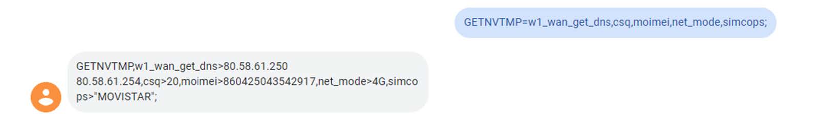
GETNVTMP=wan_ipaddr;

APPENDIX 1: NVRAM parameter list
Setup
Basic setup
WAN port setting
| No. | parameter item | parameter | value, description | example | |
|---|---|---|---|---|---|
| 1 | Connection type | wan_proto | disabled | disable | nvram set wan_proto=dhcp |
| dhcp | Dhcp mode | ||||
| static | Static IP mode | ||||
| pppoe | Pppoe dial mode | ||||
| pptp | Pptp mode | ||||
| l2tp | l2tp mode | ||||
| 3g | 3g link-1 mode | ||||
| 3glink | 3g link-2 mode | ||||
4glink
| No. | parameter item | parameter | value, description | example | |
|---|---|---|---|---|---|
| 1 | username | ppp_username | 63 bytes of longest character | nvram set ppp_username =card |
|
| 2 | password | ppp_passwd | 63 bytes of longest character | nvram set ppp_passwd=card | |
| 3 | Call center number | wan_dial | 0 | *99***1# | nvram set wan_dial=1 |
| 1 | *99# | ||||
| 2 | #99***1# | ||||
| 3 | #777 | ||||
| 4 | *98*1# | ||||
| 4 | APN | wan_apn | 63 bytes of longest character | nvram set wan_apn=3gnet | |
| 5 | PIN | wan_pin | Must be 4-byte number | nvram set wan_pin=1234 | |
| 6 | Network type selection | wan_conmode | 0 | auto | nvram set wan_conmode=0 |
| 1 | Enforce 3g | ||||
| 2 | Enforce 2g | ||||
| 3 | 3g first | ||||
| 4 | 2gfirst | ||||
| 5 | 2g/3g Allow only | ||||
| 6 | Enforce 4g | ||||
| 7 | 2g/3g/4g Allow only | ||||
| 7 | Keep online mode | KpOnlineMode | 1 | None | nvram set KpOnline Mode=1 |
| 2 | Ping mode | ||||
| 5 | Route mode | ||||
| 6 | PPP mode | ||||
| 8 | Keep online detection interval | KpOnlineInterval | Range 0-9999, in sec. | nvram set KpOnline Interval=60 |
|
| 9 | keep online to detection the main server ip | KpOnlineIcmp Dest |
Currently only support ip form,does not support domain form | nvram set KpOnlineIcmp Dest =8.8.8.8 |
|
| 10 | Keep online to detection the second server ip | KpOnlineIcmp SecDest |
Currently only support ip form,does not support domain form | nvram set KpOnlineIcmp SecDest =166.111.8. 238 |
|
| 11 | Enable dial-up failed to restart mechanism | ppp_restartppp | 0 | disable | nvram set ppp_restartppp=1 |
| 1 | enable | ||||
| 12 | Forced to reconnect | reconnect_enable | 0 | disable | nvram set reconnect_enable=1 |
| 1 | enable | ||||
Static IP
| No. | parameter item | parameter | value, description | example | |
|---|---|---|---|---|---|
| 1 | WAN IP address | wan_ipaddr | IP address form | nvram set wan_ipaddr =192.168.8.22 | |
| 2 | Subnet mask | wan_netmask | netmask | nvram set wan_netmask =255.255.255.0 | |
| 3 | gateway | wan_gateway | netmask | nvram set wan_netmask =192.168.8.1 | |
| 4 | Static DNS1 Static DNS2 Static DNS3 |
wan_dns | First DNS Second DNS Third DNS |
nvram set wan_dns=”8.8.8.8 218.85.157.99 218.85.152.99” 3 DNS directly separated by spaces,should user quotation marks separated by a space framed |
|
| 5 | Keep online mode | KpOnlineMode | 1 | None | nvram set KpOnlineMode=1 |
| 2 | Ping mode | ||||
| 5 | Route mode | ||||
| 6 | Keep online detection interval | KpOnlineInterval | Range 0-9999, in sec. | nvram set KpOnlineInterval=60 | |
| 7 | Keep online to detect main server ip | KpOnlineIcmpDest | Currently only support ip form,does not support domain form | nvram set KpOnlineIcmpDest =8.8.8.8 | |
| 8 | Keep online to detect second server ip | KpOnlineIcmpSecDest | Currently only support ip form,does not support domain form | nvram set KpOnlineIcmpSecDest =166.111.8.238 | |
Note: number 5-8 only used in the version of the dual-card
DHCP mode
| No. | parameter item | parameter | value, description | example | |
|---|---|---|---|---|---|
| 1 | Keep online | KpOnlineMode | 1 | None | nvram set KpOnlineMode=1 |
| 2 | Ping mode | ||||
| 5 | Route mode | ||||
| 2 | Keep online detection interval | KpOnlineInterval | Range 0-9999, in sec. | nvram set KpOnlineInterval=60 | |
| 3 | Keep online to detect main server ip | KpOnlineIcmpDest | Currently only support ip form,does not support domain form | nvram set KpOnlineIcmpDest =8.8.8.8 | |
| 4 | Keep online to detect second server ip | KpOnlineIcmpSecDest | Currently only support ip form,does not support domain form | nvram set KpOnlineIcmpSecDest =166.111.8.238 | |
Note: number 1-4 only used in version of the dual-card
PPPoE
| No. | parameter item | parameter | value, description | example | |
|---|---|---|---|---|---|
| 1 | User | ppp_username | 63 bytes of longest character | nvram set ppp_username=card | |
| 2 | password | ppp_passwd | 63 bytes of longest character | nvram set ppp_passwd=card | |
| 3 | Server name | ppp_service | PPPoE server address, 63 character at the longest | nvram set ppp_service =172.16.1.1 | |
| 4 | PPP compress | ppp_compression | 0 | disable | nvram set ppp_compression=0 |
| 1 | enable | ||||
| 5 | Compatible VDSL front demodulator | wan_vdsl | 0 | disable | nvram set wan_vdsl=0 |
| 1 | enable | ||||
| 6 | VLAN 8 support | dtag_vlan8 | 0 | disable | nvram set dtag_vlan8=0 |
| 1 | enable | ||||
| 7 | MPPE encrypt | ppp_mppe | 63 character at the longest | nvram set ppp_mppe=”mppe required” | |
| 8 | Single-link multi-connected | ppp_mlppp | 0 | disable | nvram set ppp_mlppp=1 |
| 1 | enable | ||||
| 9 | Keep online mode | KpOnlineMode | 1 | None | nvram set KpOnlineMode=1 |
| 2 | Ping mode | ||||
| 3 | Route mode | ||||
| 10 | Keep Online detection interval | KpOnlineInterval | Range 0-9999, in sec. | nvram set KpOnlineInterval=60 | |
| 11 | Online to keep the detection of the main server ip | KpOnlineIcmpDest | Currently only support ip form,does not support domain form | nvram set KpOnlineIcmpDest =8.8.8.8 | |
| 12 | Online to keep the detection of the second server ip | KpOnlineIcmpSecDest | Currently only support ip form,does not support domain form | nvram set KpOnlineIcmpSecDest =166.111.8.238 | |
Optional settings
| No. | parameter item | parameter | value, description | example | |
|---|---|---|---|---|---|
| 1 | Router name | router_name | 39 characters at the longest | nvram set router_name=ROUTER | |
| 2 | Host name | wan_hostname | 39 characters at the longest | nvram set wan_hostname=XXX | |
| 3 | Domain name | wan_domain | 79 characters at the longest | nvram set wan_domain =XXX | |
| 4 | MTU | mtu_enable | 0 | Auto mode | nvram set mtu_enable=1 |
| 1 | Manual mode | ||||
| wan_mtu | Digital of 0-9999 range | nvram set wan_mtu=1500 | |||
Local setting
| No. | parameter item | parameter | value, description | example |
|---|---|---|---|---|
| 1 | Local ip address | lan_ipaddr | Ip address form | nvram set lan_ipaddr=192.168.1.1 |
| 2 | Subnet mask | lan_netmask | LAN port subnet mask | nvram set lan_netmask=255.255.255.0 |
| 3 | Gateway | lan_gateway | LAN port gateway | nvram set lan_gateway =0.0.0.0 |
| 4 | Local DNS | sv_localdns | local DNS of lan port | nvram set sv_localdns=0.0.0.0 |
Network address server setting (DHCP)
| No. | parameter item | parameter | value, description | example | |
|---|---|---|---|---|---|
| 1 | DHCP type | dhcpfwd_enable | 0 | DHCP server | nvram set lan_ipaddr=192.168.1.1 |
| 1 | DHCP repeater | ||||
| 2 | DHCP server | lan_proto | dhcp | Enable | nvram set lan_netmask=255.255.255.0 |
| static | disable | ||||
| 3 | Start ip address | dhcp_start | Digital of range 1-254 | nvram set lan_gateway =0.0.0.0 | |
| 4 | The maximum number of dhcp users | dhcp_num | Digital form,with a starting ip address,and should not be greater than 254 | nvram set sv_localdns=0.0.0.0 | |
| 5 | Client lease time | dhcp_lease | Digital of range 0-99999, in minute | nvram set dhcp_lease =1440 | |
| 6 | Static DNS1 Static DNS2 Static DNS3 |
wan_dns | First DNS Second DNS Third DNS |
nvram set wan_dns=”8.8.8.8 218.85.157.99 218.85.152.99” 3 DNSdirectly separated by spaces,encountered use quotation marks separated by a space framed |
|
| 7 | WINS | wan_wins | WIN server address | nvram set wan_wins=0.0.0.0 | |
| 8 | To use DNSmasq for dhcp | dhcp_dnsmasq | 0 | disable | nvram set dhcp_dnsmasq =1 |
| 1 | enable | ||||
| 9 | To use DNSmasq for dhcp | dns_dnsmasq | 0 | disable | nvram set dns_dnsmasq =1 |
| 1 | enable | ||||
| 10 | in dhcp standard | auth_dnsmasq | 0 | disable | nvram set auth_dnsmasq =1 |
| 1 | enable | ||||
| 11 | DHCP forwarding server | dhcpfwd_ip | IP address form | nvram set dhcpfwd_ip=0.0.0.0 | |
Dynamic DNS (DDNS)
| No. | parameter item | parameter | value, description | example | |
|---|---|---|---|---|---|
| 1 | DDNS service | ddns_enable | 0 | disable | nvram set ddns_enable =1 |
| 1 | DynDNS.org | ||||
| 2 | freedns.afraid.org | ||||
| 3 | ZoneEdit.com | ||||
| 4 | No-IP.com | ||||
| 5 | custom | ||||
| 6 | 3322.org | ||||
| 7 | easyDNS.com | ||||
| 8 | TZO.com | ||||
| 9 | DynSIP.org | ||||
| 2 | type | ddns_dyndnstype | 1 | dynamic | nvram set ddns_dyndnstype =1 |
| 2 | static | ||||
| 3 | custom | ||||
| 3 | wildcard | ddns_wildcard | 1 | enable | nvram set ddns_wildcard =1 |
| other | disable | ||||
| 4 | Do not use external ip detection | ddns_wan_ip | 0 | disable | nvram set ddns_wan_ip=1 |
| 1 | enable | ||||
| 5 | Mandatory update interval | ddns_force | Digital of range 1-60, in days, the default is 10 days | nvram set ddns_force =10 | |
DynDNS
| No. | parameter item | parameter | value, description | example |
|---|---|---|---|---|
| 1 | Username | ddns_username | 64 character at the longest | nvram set ddns_username =XXX |
| 2 | Password | ddns_passwd | 3 character at the longest | nvram set ddns_passwd =XXX |
| 3 | Host name | ddns_hostname | Ddns host name of server | nvram set ddns_hostname =XXX |
freedns
| No. | parameter item | parameter | value, description | example |
|---|---|---|---|---|
| 1 | Username | ddns_username_2 | 64 character at the longest | nvram set ddns_username_2 =XXX |
| 2 | Password | ddns_passwd_2 | 3 character at the longest | nvram set ddns_passwd_2 =XXX |
| 3 | Host name | ddns_hostname_2 | Ddns host name of server | nvram set ddns_hostname_2 =XXX |
ZoneEdit
| No. | parameter item | parameter | value, description | example |
|---|---|---|---|---|
| 1 | Username | ddns_username_3 | 64 character at the longest | nvram set ddns_username_3 =XXX |
| 2 | Password | ddns_passwd_3 | 3 character at the longest | nvram set ddns_passwd_3 =XXX |
| 3 | Host name | ddns_hostname_3 | Ddns host name of server | nvram set ddns_hostname_3 =XXX |
No-IP
| No. | parameter item | parameter | value, description | example |
|---|---|---|---|---|
| 1 | Username | ddns_username_4 | 64 character at the longest | nvram set ddns_username_4 =XXX |
| 2 | Password | ddns_passwd_4 | 3 character at the longest | nvram set ddns_passwd_4 =XXX |
| 3 | Host name | ddns_hostname_4 | Ddns host name of server | nvram set ddns_hostname_4 =XXX |
Custom
| No. | parameter item | parameter | value, description | example |
|---|---|---|---|---|
| 1 | User name | ddns_username_5 | 64 character at the longest | nvram set ddns_username_5=XX |
| 2 | Password | ddns_passwd_5 | 3 character at the longest | nvram set ddns_passwd_5=XXX |
| 3 | Host name | ddns_hostname_5 | Ddns host name of server | nvram set ddns_hostname_5=XX |
| 4 | DYNDNS server | ddns_custom_5 | DYNDNS server, can generally be got in the registered server | nvram set ddns_custom_5=XX |
| 5 | URL | ddns_url | The form of character | nvram set ddns_url=XX |
| 6 | DDNS additional options | ddns_conf | DDNS additional options | nvram set ddns_conf=XX |
3322
| No. | parameter item | parameter | value, description | example |
|---|---|---|---|---|
| 1 | Username | ddns_username_6 | 64 character at the longest | nvram set ddns_username_6=XX |
| 2 | Password | ddns_passwd_6 | 3 character at the longest | nvram set ddns_passwd_6=XXX |
| 3 | Host name | ddns_hostname_6 | Ddns host name of server | nvram set ddns_hostname_6=XX |
| 4 | Type | ddns_dyndnstype_6 | The default is dynamic,can not configuration |
easyDNS
| No. | parameter item | parameter | value, description | example | |
|---|---|---|---|---|---|
| 1 | username | ddns_username_7 | 64 character at the longest | nvram set ddns_username_7=XX | |
| 2 | Password | ddns_passwd_7 | 3 character at the longest | nvram set ddns_passwd_7=XXX | |
| 3 | Host name | ddns_hostname_7 | Ddns host name of server | nvram set ddns_hostname_7=XX | |
| 4 | Wildcard | ddns_wildcard_7 | 1 | enable | nvram set ddns_wildcard_7=1 |
| other | disable | ||||
TZO
| No. | parameter item | parameter | value, description | example |
|---|---|---|---|---|
| 1 | Username | ddns_username_8 | 64 character at the longest | nvram set ddns_username_8=XX |
| 2 | Password | ddns_passwd_8 | 3 character at the longest | nvram set ddns_passwd_8=XXX |
| 3 | Host name | ddns_hostname_8 | Ddns host name of server | nvram set ddns_hostname_8=XX |
DynSIP
| No. | parameter item | parameter | value, description | example |
|---|---|---|---|---|
| 1 | Username | ddns_username_9 | 64 character at the longest | nvram set ddns_username_9=XX |
| 2 | Password | ddns_passwd_9 | 3 character at the longest | nvram set ddns_passwd_9=XXX |
| 3 | Host name | ddns_hostname_9 | Ddns host name of server | nvram set ddns_hostname_9=XX |
Wireless
Basic setup
| No. | parameter item | parameteR | value, description | example | |
|---|---|---|---|---|---|
| 1 | Wireless network mode | wl0_net_mode | disabled | Disable | nvram set wl0_net_mode= mixed |
| mixed | 801.11b/n/g | ||||
| bg-mixed | 801.11b/g | ||||
| b-only | 801.11n | ||||
| g-only | 801.11g | ||||
| ng-only | 801.11g/n | ||||
| n-only | 801.11n | ||||
| 2 | Wireless mode | wl0_mode | ap | AP mode | nvram set wl0_mode=ap |
| sta | Client mode | ||||
| infra | Adhoc mode | ||||
| apsta | Relay mode | ||||
| apstawet | Repeater bridge | ||||
| 3 | Wireless network name (SSID) | wl0_ssid | 32 character at the longest | nvram set wl0_ssid=”Matrix” | |
| 4 | Wireless channel | wl0_channel | 0 | auto | nvram set wl0_channel=6 |
| 1 | 2.412 GHz | ||||
| 2 | 2.417 GHz | ||||
| 3 | 2.422 GHz | ||||
| 4 | 2.427 GHz | ||||
| 5 | 2.432 GHz | ||||
| 6 | 2.437 GHz | ||||
| 7 | 2.442 GHz | ||||
| 8 | 2.447 GHz | ||||
| 9 | 2.452 GHz | ||||
| 10 | 2.457 GHz | ||||
| 11 | 2.462 GHz | ||||
| 12 | 2.467 GHz | ||||
| 13 | 2.472 GHz | ||||
| 5 | Channel size | wl0_nbw | 20 | 20MHz | nvram set wl0_nbw=20 |
| 40 | 40MHz | ||||
| 6 | Wireless ssid broadcast | wl0_closed | 0 | Enable | nvram set wl0_closed =0 |
| 1 | Disable | ||||
| 7 | broadband | wl0_nctrlsb | upper | upper | nvram set wl0_ nctrlsb=upper |
| lower | lower | ||||
Wireless security
| No. | parameter item | parameter | value, description | example | |
|---|---|---|---|---|---|
| 1 | Safe mode | wl0_security_mode | disabled | Disable | nvram set wl0_security_mode= psk |
| psk | WPA Personal | ||||
| wpa | WPA Enterprise | ||||
| psk2 | WPA2 Personal | ||||
| wpa2 | WPA2 Enterprise | ||||
| psk psk2 | WPA2 Personal Mixed | ||||
| wpa wpa2 | WPA2 Enterprise Mixed | ||||
| wep | WEP | ||||
| 2 | WPA algorithm | wl0_crypto | tkip | TKIP | nvram set wl0_crypto=TKIP |
| aes | AES | ||||
| tkip+aes | TKIP+AES | ||||
| 3 | WPA shared key | wl0_wpa_psk | Must be 8 63 ACSII character or 64 hexadecimal digits | nvram set wl0_wpa_psk =”123456789” | |
| 4 | Key update interval (sec.) | wl0_wpa_gtk_rekey | default: 3600, range: 1 – 99999 | nvram set wl0_wpa_gtk_rekey =3600 | |
| 5 | Radius authentication server address | wl0_radius_ipaddr | IP address format | nvram set wl0_radius_ipaddr =0.0.0.0 | |
| 6 | Radius authentication server port | wl0_radius_port | Digital of range 1-65535, default port is 1812 | nvram set wl0_radius_port=1812 | |
| 7 | Radius authentication shared key | wl0_radius_key | 79 characters at the longest | nvram set wl0_radius_key=XXX | |
| 8 | Authentication type | wl0_authmode | open | Open | nvram set wl0_authmode=open |
| shared | Shared key | ||||
| 9 | Default transmit key | wl0_keywl0_key | 1 | 1 | nvram set wl0_key=1 |
| 2 | 2 | ||||
| 3 | 3 | ||||
| 4 | 4 | ||||
| 10 | Encryption | wl0_wep_bit | 64 | 64 bits 10 hex digits/5 ASCII | nvram set wl0_wep_bit=64 |
| 128 | 128 bits 26 hex digits/13 ASCII | ||||
| 11 | ASCII/HEX | wl0_wepmode | 0 | ASCII | nvram set wl0_wepmode=1 |
| 1 | HEX | ||||
| 12 | Key 1 | wl0_key1 | 10 hexadecimal | nvram set wl0_key1=0000000000 | |
| 13 | key 2 | wl0_key2 | 10 hexadecimal | nvram set wl0_key2=0000000000 | |
| 14 | key 3 | wl0_key3 | 10 hexadecimal | nvram set wl0_key3=0000000000 | |
| 15 | Key 4 | wl0_key4 | 10 hexadecimal | nvram set wl0_key4=0000000000 | |
NAT Configuration
| No. | parameter item | parameter | value, description | example | |
|---|---|---|---|---|---|
| 1 | Port forward | forward_spec | Name of application | Letters and numbers, 18 characters at the longest | nvram set forward _spec =”xx:on:both :12>192.168.1.1: 11<192.168.2.1/ 24 yy:off:tcp:12> 192.168.1.2:10 <192.168.3.1/24 “ |
| protocol | tcp, udp, both | ||||
| Whether to open | on:enable the rule | ||||
| off: disable the rule | |||||
| Source address of data | A.B.C.D/M | ||||
| Source port of data | 1-65535 | ||||
| Destination address of forward | A.B.C.D | ||||
| Destination port of forward | 1-65535 | ||||
| format: ”Name of application:protocol: destination port of data>Destination address of forward: Destination port of forward<source address of data next rule “… | |||||
| 2 | Range of port forward | forward_port | Name of application | Letters and numbers, 18 characters at the longest | nvram set forward _port =”xx:on:udp: 1:2>192.168.7.2 yy:off:tcp:3:6>192. 168.7.3 “ |
| Whether to open | on: enable | ||||
| off: disable | |||||
| protocol | udp, tcp, both | ||||
| Starting destination port of data | 1-65535 | ||||
| The end of destination port of data | 1-65535 | ||||
| Destination port of forward | A.B.C.D | ||||
| format: ”application:protocol: destination port of data>Destination address of forward: Destination port of forward<source address of data next rule “… | |||||
| 3 | Port trigger | port_trigger | Name of application | Letters and numbers 18 characters at the longest | nvram set port_trigger = “zzz:on:tcp:2-555> 6-666 ttt:on:both:5-66 >88-9099 yyy:on:udp :2-555>6-666 ttt:on: both:5-66>88-9099” |
| Whether to open | on: enable | ||||
| off: disable | |||||
| protocol | tcp, udp,both | ||||
| Starting port number of destination port range Of Trigger rule | 1-65535 | ||||
| The end of port number of destination port range Of Trigger rule | 1-65535 | ||||
| Starting port number of port range Of Trigger rule | 1-65535 | ||||
| The end of port number of port range Of Trigger rule | 1-65535 | ||||
| format: ”Name of application:protocol:Starting port number of destination port range Of Trigger rule: The end of port number of destination port range Of Trigger rule>Starting port number of port range Of Trigger rule:The end of port number of port range Of Trigger rule;next rule “… | |||||
| 4 | enable DMZ | dmz_enable | 0 | Disable DMZ | nvram set dmz_enbale=1 |
| 1 | Enable DMZ | ||||
| 5 | DMZ host ip address | dmz_ipaddr | 1-254 | Nvram set dmz_ipaddr=23 | |
Application
Serial port application
| No. | parameter item | parameter | value, description | example | |
|---|---|---|---|---|---|
| 1 | Serial port application | ser_app_en | 0 | disable | nvram ser_app_en=0 |
| 1 | enable | ||||
| 2 | 4 | 2400 | nvram set ser_baudrate1 =10 | ||
| 5 | 4800 | ||||
| 6 | 9600 | ||||
| 7 | 19200 | ||||
| 8 | 38400 | ||||
| 9 | 57600 | ||||
| 10 | 115200 | ||||
| 3 | Data-bits | ser_databit1 | 1 | 8 digit | nvram ser_databit1=1 |
| 2 | 7 digit | ||||
| 3 | 6 digit | ||||
| 4 | Stop-bit | ser_stopbit1 | 1 | 1 digit | nvram set ser_stopbit1=1 |
| 2 | 2 digit | ||||
| 5 | inspect | ser_parity1 | 1 | none | nvram set ser_parity1=1 |
| 2 | Odd parity | ||||
| 3 | Even parity | ||||
| 6 | Fluid control | ser_flowcontrol1 | 1 | none | nvram set ser_flowcontrol1=1 |
| 2 | hardware | ||||
| 3 | software | ||||
| 7 | Protocol type | ser_submodesw | 1 | UDP(DTU) | nvram set ser_submodesw =1 |
| 2 | Pure UDP | ||||
| 3 | TCP(DTU) | ||||
| 4 | Pure TCP | ||||
| 5 | TCP server | ||||
| 6 | TCST | ||||
| 8 | Server address | ser_remoteip | a form of IP address or domain name | nvram set ser_remoteip =120.42.46.98 | |
| 9 | Server port | ser_remoteport | decimal figures of 1-65535 range | nvram set ser_remoteport =5501 | |
| 10 | Equipment number | ser_dtuid | Digital format,13 byte at the longest | nvram set ser_dtuid =12345678910 | |
| 11 | Equipment ID | ser_dtudeviceid | Digital format, must be 8 digit,otherwise an error | nvram set ser_dtudeviceid =12345678 | |
| 12 | Heartbeat interval | ser_onlnrptintvl | decimal figures of 1-99999 range | nvram set ser_onlnrptintvl =60 | |
| 13 | Listening port | ser_tcpsvr_listen_port | decimal figures of 1-65535 range | nvram set ser_tcpsvr_listen_port =6666 | |
| 14 | Custom heartbeat packets | ser_tcp_custom_hrt | A maximum of 50 bytes | nvram set ser_tcp_custom_hr t=XXX | |
| 15 | Custom registration package | ser_tcp_custom_reg | A maximum of 50 bytes | nvram set ser_tcp_custom_reg =XXX | |
Management
Management
| NO. | parameter item | parameter | value, description | EXAMPLE | ||
|---|---|---|---|---|---|---|
| 1 | protocol | HTTP | http_enable | 1 | enable | nvram set http_enable=1 |
| other | disable | |||||
| HTTPS | https_enable | 1 | enable | nvram set https_enable=0 | ||
| other | disable | |||||
| 2 | Auto refresh (sec.) | refresh_time | decimal figures of 1-99 range | nvram set refresh_time =3 | ||
| 3 | Display system information page before landing | status_auth | 1 | enable | nvram set status_auth =1 | |
| 0 | disable | |||||
| 4 | Password protection of system information page | info_passwd | 1 | enable | nvram set info_passwd =0 | |
| other | disable | |||||
| 5 | Web interface management | remote_management | 1 | enable | nvram set remote_management =0 | |
| 0 | disable | |||||
| 6 | Use HTTPS | remote_mgt_https | 1 | enable | nvram set remote_mgt_https=0 | |
| other | disable | |||||
| 7 | Web interface port | http_wanport | decimal figures of 1-65535 range | nvram set http_wanport =8088 | ||
| 8 | SSH management | remote_mgt_ssh | 0 | disable | nvram set remote_mgt_ssh=1 | |
| 1 | enable | |||||
| 9 | SSH remote port | sshd_wanport | decimal figures of 1-65535 range | nvram set sshd_wanport =22 | ||
| 10 | Telnet management | remote_mgt_telnet | 0 | disable | nvram set remote_mgt_telnet =0 | |
| 1 | Enable | |||||
| 11 | language | language | chinese_simplified | chinese | nvram set language=english | |
| english | english | |||||
Remain active
| no. | parameter item | parameter | value, description | example | ||
|---|---|---|---|---|---|---|
| 1 | Timer switch | schedule_bs_enable | 1 | enable | Nvram set schedule_bs_enable=0 | |
| 0 | disable | |||||
| 2 | matching | schedule_mode | 1 | Day of month | nvram set schedule_mode=1 | |
| 2 | Week of month | |||||
| 3 | period of time a month | |||||
| 4 | period of time a week | |||||
| 3 | Off time | hour | shutdown_hours | decimal figures of 0-23 range | nvram set shutdown_hours=0 | |
| minute | shutdown_minutes | decimal figures of 0-59 range | nvram set shutdown_minutes=0 | |||
| 4 | Shutdown date | Start day of month | shutdown_day | 0-31 range, 0 is everyday | nvram set shutdown_day=0 | |
| End day of month | shutdown_day_e | decimal figures of 1-31 range | nvram set shutdown_day_e=1 | |||
| Start day of week | shutdown_week | * | Every day | nvram set shutdown_week=0 | ||
| 0 | sunday | |||||
| 1 | monday | |||||
| 2 | thesday | |||||
| 3 | wednesday | |||||
| 4 | thursday | |||||
| 5 | friday | |||||
| 6 | saturday | |||||
| Weeks after the end of days | shutdown_week-_e | decimal figures of 0-6 range | nvram set shutdown_week_e=0 | |||
| 5 | Boot time | hour | boot_hours | decimal figures of 0-23 range | nvram set boot_hours=0 | nvram set ser_parity1=1 |
| minute | boot_minutes | decimal figures of 0-59 range | nvram set boot_minutes=0 | nvram set boot_minutes=0 | ||
| 6 | Boot date | Start day of month | boot_day | 0-31 range, 0 is everyday | nvram set boot_day=0 | |
| End day of month | boot_day_e | decimal figures of 1-31 range | nvram set boot_day_e=1 | |||
| start day of week | boot_week | * | Weekday | nvram set boot_week=0 | ||
| 0 | sunday | |||||
| 1 | monday | |||||
| 2 | tuesday | |||||
| 3 | wednesday | |||||
| 4 | thursday | |||||
| 5 | friday | |||||
| 6 | saturday | |||||
| The end of week day | boot_week¬_e | decimal figures of 0-6 range | nvram set boot_week_e=0 | |||
| 7 | Scheduled reboot | schedule_enable | 1 | enable | nvram set schedule_enable =0 | |
| 0 | disable | |||||
| 8 | Scheduled reboot options | schedule_hour_time | 1 | Interval mode | nvram set schedule_hour_time=1 | |
| 2 | Set the time mode | |||||
| 9 | interval (sec.) | schedule_time | decimal figures of 60-99999 range | nvram set schedule_time =3600 | ||
| 10 | At the set time | hour | schedule_hours | decimal figures of 0-23 range | nvram set schedule_weekdays=00 | |
| minute | schedule_minutes | decimal figures of 0-59 range | ||||
| week | schedule_weekdays | * | everyday | |||
| 00 | sunday | |||||
| 01 | monday | |||||
| 02 | tuesday | |||||
| 03 | wednesday | |||||
| 04 | thursday | |||||
| 05 | friday | |||||
| 06 | saturday | |||||

 Enter the “ethernet” or “modem” connection type:
 For an ethernet configuration, make sure the IP parameters are compatible with server access according to the concentrator local network configuration. For an ethernet connection, the configuration must be compatible with the concentrator’s local network topology so that it can access the servers. This configuration is done from the “Networks” configuration page (see section 3.2.2.3: “Networks”).
For a modem connection, the modem configuration must be correct before a connection can be set up. This configuration is done from the “Modem” configuration page (see section 3.2.2.4: “Modem”).
The parameters for the servers to be configured are at least the following:
For an ethernet configuration, make sure the IP parameters are compatible with server access according to the concentrator local network configuration. For an ethernet connection, the configuration must be compatible with the concentrator’s local network topology so that it can access the servers. This configuration is done from the “Networks” configuration page (see section 3.2.2.3: “Networks”).
For a modem connection, the modem configuration must be correct before a connection can be set up. This configuration is done from the “Modem” configuration page (see section 3.2.2.4: “Modem”).
The parameters for the servers to be configured are at least the following:
 Therefore the following fields need to be configured: “Interface”, “Type”, “Server type”, “Address”, “Port”, “Login” and “Password”.
The other fields can be left at the default values subject to the directories having been properly created beforehand. See section 3.1.2: “Configuration files” for more details.
Therefore the following fields need to be configured: “Interface”, “Type”, “Server type”, “Address”, “Port”, “Login” and “Password”.
The other fields can be left at the default values subject to the directories having been properly created beforehand. See section 3.1.2: “Configuration files” for more details.


 Wait. The concentrator will reboot using its factory configuration.


