DB15 expansion connection: 3 digital inputs (2 of them pulse counters), 2 digital outputs and 2 A/D conversors (0-50V in tension mode, 0-20mA in current mode)
Serial interfaces: 1x RS232 (DB9) or 1x RS485 (configurable with switches)
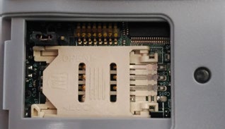
Wavecard 868MHz: internal radio card, connected to secondary port
MTX-Tunnel software uses these inputs/outputs as follows:
GPIO
LOCATION
PIN
I/O
FUNCTION
@MODBUS
GPIO1
DB15
4
Digital input
Wake up/pulse counter
1/13-14
GPIO2
DB15
11
Digital input
SMS alarm/pulse counter
2/15-16
GPIO3
DB15
9
Digital input
User/pulse counter
3/17-18
GPIO4
DB15
5
Digital output
User
4
GPIO5
DB15
12
Digital output
User
5
ADC1
DB15
15
Analog input
User
11
ADC2
DB15
13
Analog input
User
12
VExt
DB15
10
Output voltage
4V
—
GND
DB15
14
Ground
Ground
—
The column “GPIO” indicates the virtual GPIO corresponding to the GSM module inside the modem
The column “Location” informs us which modem connector is located the I/O
The column “Pin number” tells us the I/O terminal block or connector pin number
The column “I/O” tells us if the GPIO is an input (digital or analog) or a digital output
The column “Function” tells us if the GPIO has special features in MTX-Tunnel. If it doesn’t use “SMS alarm” or “Wake up” you can use GPIO1 and GPIO2 as user digital inputs.If it uses them, digital inputs are used by the MTX-Tunnel
The parameters OUTPUT_xxx1 refer to PIN 5 of the DB15 connector
The parameters OUTPUT_xxx2 refer to PIN 12 of the DB15 connector
GPIO1 and GPIO2 are optoisolated inputs that can be activated via GND (PIN 14 of the DB15 connector). GPIO3 is a CMOS digital input, activated via VOUT (PIN 10) of the DB15 connector
Jumpers configuration
The modem has serveral switches that allow several configurations:
[SW5 off] + [SW2 on] + [SW1 on]: RS232 DB9 on, RS232 DB15 off, RS485 off
Start by checking that the computer’s IP parameters are compatible with the WebdynSunPM IP address (by default 192.168.1.12)
Launch a web browser (Chrome, Firefox, Edge, Safari, etc.) and enter the WebdynSunPM concentrator IP address in the address bar. An authentication page is displayed:
There are two configuration solutions, using the web interface and using text messages:
Configuration using the web interface:
Start by establishing a connection to the concentrator by connecting to it to access the server configuration:
Enter the “ethernet” or “modem” connection type:
For an ethernet configuration, make sure the IP parameters are compatible with server access according to the concentrator local network configuration. For an ethernet connection, the configuration must be compatible with the concentrator’s local network topology so that it can access the servers. This configuration is done from the “Networks” configuration page (see section 3.2.2.3: “Networks”).
For a modem connection, the modem configuration must be correct before a connection can be set up. This configuration is done from the “Modem” configuration page (see section 3.2.2.4: “Modem”).
The parameters for the servers to be configured are at least the following:
Therefore the following fields need to be configured: “Interface”, “Type”, “Server type”, “Address”, “Port”, “Login” and “Password”.
The other fields can be left at the default values subject to the directories having been properly created beforehand. See section 3.1.2: “Configuration files” for more details.
Text message configuration:
Text message configuration requires sending the following commands:
Apn: to configure the SIM card APN. (see section 3.2: ““apn” modem configuration command)
Ftp: to configure the FTP server that will contain the concentration configuration (see section 3.3: ““ftp” FTP configuration command”).
Connect: to launch the connection to the FTP server and load the configuration (see section 3.1: ““connect” connection command
Access to the FTP server depends on the selected solution.
If you have chosen a portal, it will give you the FTP server access identifiers.
If you want to use your own FTP server, contact your network administrator.
For all other configurations, and to determine the best solution, contact the Webdyn sales department which will advise you and direct you to the relevant contacts: contact@webdyn.com
There are 2 methods to force a concentrator factory reset:
Press the Factory Reset button on the concentrator for 20 seconds:
Wait. The concentrator will reboot using its factory configuration.
If a SIM card is installed and configured, a “factory” text message can also be used for factory reset. Just send the “factory” text message to the SIM card phone number (see section 3.7: ““factory” reset command”)
Yes, different Modbus devices can be connected to the same serial port.
Device compatibility:
Same type of RS485 or 4 wire connection.
All devices should be able to be configured using identical bus specifications. Same speed, same parity, same number of stop bits and data bits on all devices and on the WebdynSunPM.
Each device must be assigned a unique Modbus address (between 1 and 247) on the bus. (UnitID)
No, the concentrator is not able to decrypt data from WM-BUS equipment because it does not have a safe on board to guarantee the security of the encryption keys of your equipment. The recovered data is deposited without modification (without decryption) by the concentrator on your remote server.
the battery level: if the battery level is too low or empty, the product will not run properly or not run at all.
Modem reception level: a bad signal at the modem may also prevent the hub from uploading files. Look to move the product or install an external antenna to improve signal quality.
The last configuration file: a bad configuration file can block the product.
Replace the product and inject the configuration from the old product into the new one. If a white list is used, remember to inject it into the new product as well.
Warning – Firmware update V4.07.02 –For the old version with SIM CARD of the pin code is 0000 you can update in this version.
For the second case : When you insert a SIM CARD with pin code is 0000 used in this version (4.07.02) Downgrading to a previous version is not permitted.
There are two types of configuration: via the web interface or via SMS.
Configuration of the web interface:
1/ Go to the configuration page with the gateway IP address (default 192.168.1.12)
2/ Go to the Configuration tab.
3/ Select either the Ethernet or modem connection mode:
If connecting via the local network (Ethernet):
Edit the WebdynSun’s IP parameters by assigning it a network-compatible address.
Please note, all fields must be completed in accordance with the configuration of your local network.
If connecting via the GPRS network (Modem):
Change the connection settings of the GPRS modem to the settings provided by your mobile operator.
4/ Edit the FTP server parameters.
5/ Confirm the changes.
6/ Restart the WebdynSun gateway using the new settings.
7/ In the menu, click on the “installation” tab, followed by the “connection” sub-tab and start the connection.
Configuration via SMS:
This configuration method requires the use of an active SIM card with a data option and a pin code that must be either “0000” or disabled. The SIM card must be inserted into the unit before connection to the mains supply. After connection to the mains supply, send the following SMS messages to the number of the previously inserted SIM card:
SMS for configuring the APN: After replacing the generic fields with those of your operator, send the following SMS*: apn=apn_name;usr=user_name;pwd=password;
Replace the above SMS fields with the following information:
apn_name: APN name supplied by your mobile operator
user_name: APN ID supplied by your mobile operator
password: APN password supplied by your mobile operator
SMS for FTP configuration: After replacing the generic fields with those of your FTP server, send the following SMS*: Ftp=server_name:user_name:password:port;
Replace the above SMS fields with the following information:
server_name: FTP server address
user_name: FTP account ID
Password: FTP account password
Port: FTP server port (the default port is 21)
Connection SMS:
Send the word “connect” by SMS* to launch a connection to the FTP server
*Please note: the formatting of the SMS must be exactly identical to that shown above (e.g.: no spaces between characters, etc.)
Put the DIP Switch 2 on the WebdynSun card in “ON” position
Start the WebdynSun by connecting it only to the mains power supply
Wait until all the LEDs flash and then stop flashing (3 to 5 mins).
Disconnect from the mains
Reset the Dip Switch 2 to “OFF”
Reconnect the battery
Reconnect to the mains supply and the WebdynSun starts normally.
If there is a SIM card inserted in the unit:
Send an SMS message containing the word “factory” to the number of the inserted SIM card.
NB : Resetting the gateway restores the configuration to its original state. Please note: data will be saved but the specific settings will not. Therefore, all the settings must be reconfigured.
Therefore, if the remote server cannot be accessed, the WebdynSun gateway can backup data for several months. The maximum data backup time varies depending on the amount of data to be collected.
The average backup time ranges from 3 to 4 months.
Yes, data may be sent to a PLC if the latter is equipped with a Modbus protocol. The “Report” configuration file allows the WebdynSun gateway to automatically write the values read on a Modbus slave
Different brands of inverter may be connected to the RS485(B) port or via the Ethernet port if the inverter protocol is based on the Modbus protocol (RTU or TCP).
However, different brands of inverters cannot be connected to the same RS485(A) port.
Yes, different Modbus devices can be connected to the same RS485 (B) port.
However, they must have the same communication parameters (bus parameters or compatible IP parameters), in order for them to communicate with each other.
Warning – Firmware update V4.07.02 –For the old version with SIM CARD of the pin code is 0000 you can update in this version. For the second case : When you insert a SIM CARD with pin code is 0000 used in this version (4.07.02) Downgrading to a previous version is not permitted.
Warning – Firmware update V4.07.02 – For the old version with SIM CARD of the pin code is 0000 you can update in this version.
For the second case : When you insert a SIM CARD with pin code is 0000 used in this version (4.07.02) Downgrading to a previous version is not permitted.
If the file is deleted from the directory after connecting the WebdynRF gateway, the problem is usually due to a file format error. The configuration and control files must follow the format described in the schema (XSD) files.
To check schema consistency, open the XML file with the Notepad++ text editor and install the “XML Tool” add-on. Next, copy the corresponding XSD file to the XML file in the same directory, and select “Validate now” in XML Tool. Errors detected by the tool should be displayed.
If the file is not deleted from the server, the most common problem is that the file has not been located correctly. The file must be available on the server in the “INBOX” directory and in the sub-directory bearing the product UID name (e.g.: “/INBOX/0045CE/”).
There are 2 firmware updating methods: Local updating: On the WebdynRF configuration interface, go to the “Actions” tab and select the updater in the “File upload” menu before clicking on the “Upload” button
Remote updating: Upload the file containing the updater (file with extension “.bz2”) in the “BIN” directory to the FTP server . Next, place the update command in the INBOX directory corresponding to your gateway (“INBOX/”, with, the identifier of the gateway concerned)
The update command must follow the following format:
updater.tar.bz2 checksum_md5
updater.tar.bz2 checksum_md5
With:
updater.tar.bz2: Updater file name uploaded to the “BIN” directory
A lack of connection to the FTP server may be due to a network connection problem (Ethernet or GPRS), an FTP login problem or a failure to initiate the connection.
If you cannot connect to the network, check the following points:
Ethernet:
Modem set to “off” or “always off”
“Gateway” fields correctly entered
At least one DNS server must be configured
GPRS:
Modem set to “on”
APN, APN ID and APN password correctly entered
GPRS call number set to “*99***1#”
If you cannot log in, check the following points:
Incorrect FTP parameters
TCP port 21 closed at output
Domain name resolution problem: the DNS server is not specified
If the connection fails to initiate:
In this case, only the automatic connection does not work. The problem is probably caused by an incorrect schedule configuration. Please note, the schedule ID must be an integer.
PARTICULAR APPLICATION OF THE WEBDYNRF WIRELESS M-BUS GATEWAY
For the WM-bus module data to be transmitted, you must:
Choose the mode corresponding to the modules used (S, T or N)
Define the modules or groups of modules to be processed
A module may be defined in a unique way by all the fields below:
Id
Manufacturer
Version
Medium
If a module’s data is encrypted, the encryption key for this module can be defined in the “Key” field.
To simplify the entry of the modules to be processed, a module group can be defined that conforms to the fields entered. The other fields will then be left empty (below is an example of a configuration for retrieving all Webdyn manufacturer (WDN) modules with the encryption key “00000000000000000000000000000000”.
Id :
Manufacturer : WDN
Medium :
Version :
Label : Webdyn
Key : 00000000000000000000000000000000
Note: In order for the modules (filters) entered to be taken into account, the “ByPass filter” mode must be deactivated.
The statuses transmitted by the WebdynRF gateway are the raw values contained in the Wavenis modules. They are transmitted without interpretation. For further details, please refer to the Coronis module manuals.
Annexes et autres documents
WARNING : Pour les anciens produits qui disposent d’une carte SIM avec un code PIN à 0000 , la mise à jour vers la version 4.07.02 sera fonctionelle.
Second cas : Si la carte SIM avec un code PIN à 0000 est utilisée dans cette version (4.07.02), le passage vers une mise à jour antérieure est interdit.
We use cookies to ensure that we give you the best experience on our website. If you continue to use this site we will assume that you are happy with it.

 Enter the “ethernet” or “modem” connection type:
 For an ethernet configuration, make sure the IP parameters are compatible with server access according to the concentrator local network configuration. For an ethernet connection, the configuration must be compatible with the concentrator’s local network topology so that it can access the servers. This configuration is done from the “Networks” configuration page (see section 3.2.2.3: “Networks”).
For a modem connection, the modem configuration must be correct before a connection can be set up. This configuration is done from the “Modem” configuration page (see section 3.2.2.4: “Modem”).
The parameters for the servers to be configured are at least the following:
For an ethernet configuration, make sure the IP parameters are compatible with server access according to the concentrator local network configuration. For an ethernet connection, the configuration must be compatible with the concentrator’s local network topology so that it can access the servers. This configuration is done from the “Networks” configuration page (see section 3.2.2.3: “Networks”).
For a modem connection, the modem configuration must be correct before a connection can be set up. This configuration is done from the “Modem” configuration page (see section 3.2.2.4: “Modem”).
The parameters for the servers to be configured are at least the following:
 Therefore the following fields need to be configured: “Interface”, “Type”, “Server type”, “Address”, “Port”, “Login” and “Password”.
The other fields can be left at the default values subject to the directories having been properly created beforehand. See section 3.1.2: “Configuration files” for more details.
Therefore the following fields need to be configured: “Interface”, “Type”, “Server type”, “Address”, “Port”, “Login” and “Password”.
The other fields can be left at the default values subject to the directories having been properly created beforehand. See section 3.1.2: “Configuration files” for more details.


 Wait. The concentrator will reboot using its factory configuration.


