Titan – AN18: Web Control and Data Collection Platform for Routers and Modems with Tunnel

Looking for something else?

Titan – AN18: Web Control and Data Collection Platform for Routers and Modems with Tunnel

Introduction

Titan routers and modems with MTX-Tunnel firmware have the ability to send data to web platforms. Data that can be collected from sensors, but also own data, such as IP address, coverage, firmware version, etc. It is also possible to communicate with them from a web platform to execute actions, such as a configuration change or the execution of a reset.

This application note is intended to be a utility for those users who want to build a small web platform for collecting data or simply monitoring their own equipment.

Data Transmission of the Titan Routers and MTX-Tunnel Modems

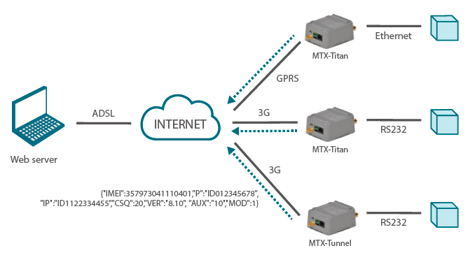
Titan routers and MTX-Tunnel modems have 2 types of data transmission. On the one hand the data of own state (IP, coverage, …). On the other hand the data of your internal datalogger. Both types of data can be sent via HTTP or HTTPS to the web platform.

Imagine that we want to make a simple web page showing a list of MTX devices that we have installed in the field. In this page we will show, for each MTX, its name, its current IP address, the GSM coverage level (rssi/csq), the date and time of the last MTX communication with the platform, the MTX model and The firmware version.

That is, we will configure the Titan routers and modems with MTX-Tunnel firmware so that periodically (or whenever they change their IP address) they communicate with a web platform to report on their status. As an example, we want to design a web page like the one shown in the following figure:

Modems with MTX-Tunnel firmware and Router Titan can send their status data to a Web Platform via HTTP GET/HTTPS GET. In both cases the encapsulated data can be sent to a JSON object, which simplifies the use of the same as it allows the scalability for new data sent in future firmware versions.

Status data sent by Modems with MTX-Tunnel firmware and Router Titan are very similar.

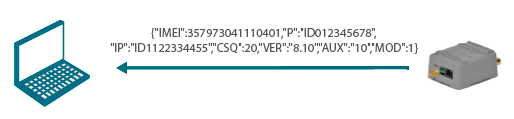
Example of Sending Status Data from a Modem with MTX-Tunnel Firmware:

{IMEI:357973041110401,P:ID012345678,IP:ID1122334455,CSQ:20,VER:8.10, AUX:10,MOD:1}

Where:
IMEI: internal identification of the MTX
P: KEYID of the device defined in the DNS_password parameter
IP: Current MTX IP
CSQ: MTX gsm coverage (0 … 31)
VER: MTX-Tunnel firmware version
AUX: CustomData
MOD: MTX Modem Model

Example of Sending Status Data from a Router Titan:

{TYPE:DNS,IMEI:357044060009633,IP:95.126.36.167,P:ID12345678,RSSI:16,MOD:101,VER:3.00.3.15}

Where:
TYPE: Indicates the type of information sent
IMEI: internal identification of the MTX
P: KEYID of the device defined in the DNS_password parameter
IP: Current MTX IP
RSSI: MTX gsm coverage (0 … 31)
VER: MTX-Tunnel firmware version
MOD: MTX Modem Model

Configuration of the Titan Router to Send Status Data to the Web Platform

Setting up a Titan router to periodically send your status data to a Web Platform is very simple. Just go to the configuration menu Other> Private DynDNS and configure the router in a similar way to the following figure:

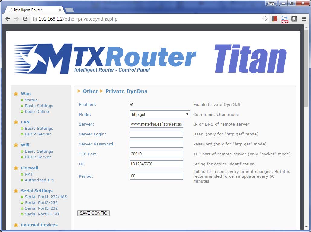
That is, we activate the Enabled box, specify the HTTP GET mode, indicate the complete URL where to dump the data (without http/https), such as “www.metering.es/json/set.asp? Data =, and then in the field ID we can indicate the KEYID of the device. This will be used by the platform to identify the device. In the field Period we indicate the period (in minutes) of sending status data to the Web Platform. Remember that in case of a change of IP in the Router will also make a sending of status data, informing your new IP immediately.

With the data configured in the previous screen, the Titan router, every 60 minutes, will send its status data to www.metering.es/json/set.asp?data=, that is, from the data variable we will retrieve The JSON object with the status data.

Configuration of Modems with MTX-Tunnel to Send Status Data to Web Platform

The configuration of a Modem with MTX-Tunnel firmware is also very simple, but instead of making the configuration graphically it is done in the usual way MTX-Tunnel, that is, through a configuration file named config. Txt . It would be enough to add the following lines to the configuration file:

DNS_enabled: on
DNS_mode: http
DNS_httpMode: json
DNS_password: ID1122334455
DNS_server: www.metering.es/json/set.asp?data=
DNS_period: 1800
DNS_aux: customData
DNS_extended: off

Where,
DNS_enabled on indicates that the status data must be sent periodically
DNS_mode http indicates that the HTTP GET method must be used
DNS_httpMode json indicates that the data sent must have the format JSON
DNS_server indicates the full URL to where we want to send the data
DNS_period specifies the period (in seconds) of sending status data
DNS_aux: can be used for sending user data
DNS_extended: off we indicate that we do not want to send us the digital and analog I/O.
If we wanted the modem to enter in the JSON such data we would put on

With this configuration, the Modem with MTX-Tunnel firmware will send its status data to the www.metering.es/json/set.asp?data= every 1800 seconds (30 minutes).

Send Data from Web Platform to a Router or Modem with MTX-Tunnel Firmware

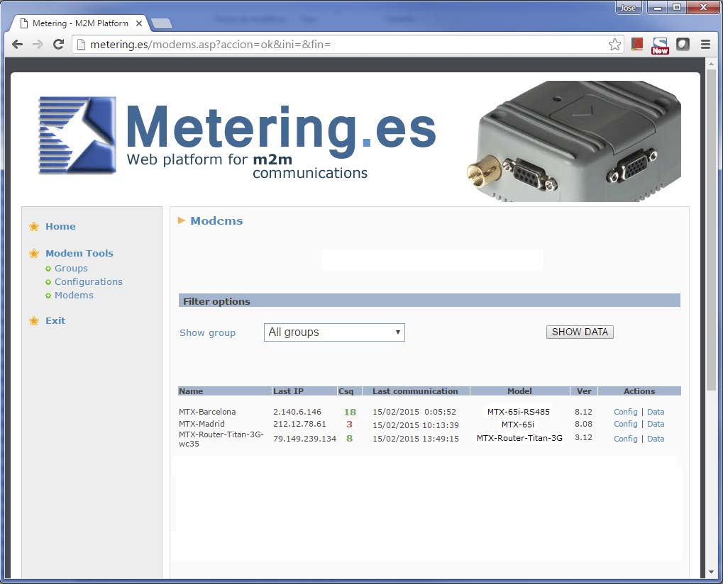
At this point we would be ready to create a Web Platform for collecting the status of remote devices. Something like the one shown below. Whit this, we can list that information from the data received periodically from each device, that is, its last IP, the coverage value, etc.

This is great, we can see the status of our remote devices in real time, detect problems (communication, low coverage, etc.). But we may need to take some action on the Modem / Router from the web platform itself. Imagine that we want to commute a relay, how would we do it?

Both the Titan Router and the Modems with MTX-Tunnel firmware have their own API to perform certain actions. This API basically consists of a set of AT commands. If you are a user of the Titan Router and modems with signature MTX-Tunnel you will know that these AT commands can be sent to the modem in many ways depending on the device: TCP socket, Telnet, HTTP GET, SMS, RS232 / 485, Modbus TCP, SNMP… Refer to the user manual to discover all AT commands available on each platform as well as how to use them.

For the present example we will focus on the commands:

AT^SSIO=0,0 It allows to activate a digital output in a modem with MTX-Tunnel
AT^MTXTUNNEL=SETRELAY,0,1 It allows to activate the internal relay of the Titan router

We want to switch the modem digital output or the Router Titan relay from the web. The web would only have to send, in response to an HTTP GET sending of the Modem/Router, something as simple as:

<MTXTUNNELR>AT^SSIO=0,0</MTXTUNNELR> for MTX-Tunnel
<MTXTUNNELR>AT^MTXTUNNEL=SETRELAY,0,1</MTXTUNNELR> for Titan

That easy. As soon as the Modem or Router connects to the platform to send data, the web platform will send this command and we will be able to observe how the relay switches.

Change the Complete Configuration of MTX-Tunnel Modem from the Web Page

There are several ways to change the configuration of a MTX-Tunnel modem from a web platform. The procedure would be exact to previous example of the switching of a relay. The only change we have to make is the AT command itself. In this case, the response command we would send would be:

<MTXTUNNELR>AT^MTXTUNNEL=SETCONFIG,
COMM_baudrate: 115200
COMM_bitsperchar: 8
….
….
DNS_AUX: 11
TELNET_enabled: on
TELNET_login: user
TELNET_password: 1234
CSD_enabled: off
</MTXTUNNELR>

Once this is done, the modem will reboot automatically and we would have the new configuration.

How can we know the configuration version that has a certain MTX-Tunnel modem so that the web platform can decide whether to update its configuration or not to update it?

A simple way is to use the DNS_AUX configuration parameter. Recall, as indicated in the first pages of this application note, each time the MTX-Tunnel modem communicates with the web platform sends an AUX parameter:

{IMEI:357973041110401,P:ID012345678,IP:ID1122334455,CSQ:20,VER:8.10, AUX:10,MOD:1}

This parameter corresponds to the DNS_AUX value of the configuration file config.txt. For example, if we receive the AUX parameter of the MTX-Tunnel modem with a value of 10 and it does not match the one of the platform (imagine that the current configuration version is 11), we will make the web platform send the New configuration to the MTX-Tunnel. Obviously the new configuration sent to the modem would contain the DNS_AUX: 11 field.
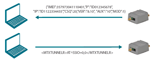
As a schematic:

The modem with MTX-Tunnel firmware sends its status periodically. The AUX field returns a value of 10 because in its configuration file the DNS_aux parameter is 10.

The Web Platform detects that the 10 configuration is obsolete and sends a new 
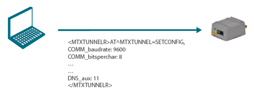
configuration, in which the DNS_aux parameter will be 11.

Send AC Commands to Devices with MTX-Tunnel in Real Time

We have shown how to build a small web control platform that allows us to periodically receive the status of modems and routers and perform an action on them every time a communication is received.

In other scenarios it may be necessary to perform an action on a modem/router at any given time, without having to wait for the modem to communicate with the Web Platform. For this, the MTX Tunnel Modems and the Router Titan incorporate a special configuration. This configuration causes these devices to open a TCP socket permanently against the IP address (or DNS) of the Web Platform to a certain TCP port. By means of this permanent TCP connection we can send AT commands to the MTXTunnel Modem and Router Titan at any time, that is, to execute actions in real time.

In this case we will have to develop a web page that supports sockets server. This is a page php, asp. net, java… that allows to manage these connections coming from each team. In this application note will not enter the programming of the website, but in the appropriate configuration of the Modems MTXTunnel and Router Titan to be able to establish such communication channel in real time.

Router Configuration to Receive Commands Sent from Web Platform in Real Time

In order to send commands in real time to a Titan router from a web platform we must configure a TCP communication socket on the router that will be permanently established against the platform. To do this we must configure the router Titan in the following way.

Other > Console menu and configure the different parameters in the same way as the following figure:

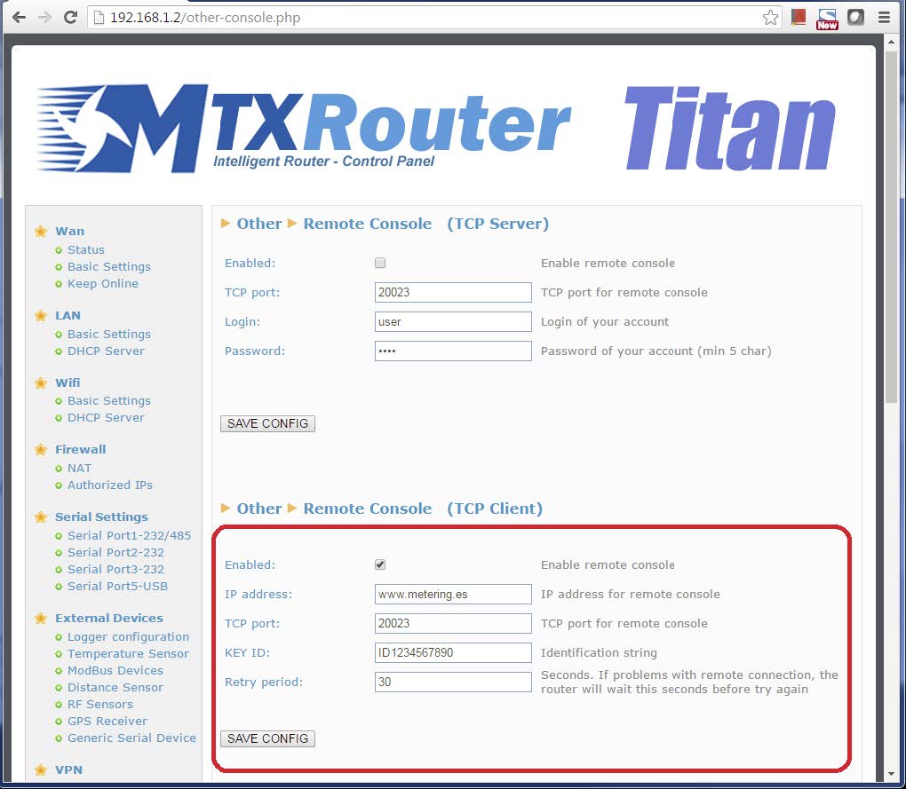
That is, we activated the console in TCP Client mode (connection FROM THE modem TOWARDS the Web Platform). We indicate the IP address (dns) and TCP port to where we want to connect the Router Titan, a KEYID with which the TITAN router will be identified in the Web Platform and a retry period. That is, a pause time after which, in case of fall of the socket, the connection is again retried.

The KEYID is the first thing that the Titan Router will transmit through the socket once established. It must be used by the Web Platform to identify the remote computer and accept or not a connection.

Once the LINK is established it is possible to send any command to the modem. For example, if at any given moment we want a Router Titan to initiate an OpenVPN connection against another router, we could send a command to open a 10-minute client OpenVPN session against IP 1.2.3.4 and port 1194:

<MTXTUNNELR>AT^MTXTUNNEL=OVPNX,10,1.2.3.4,1194</MTXTUNNELR>

To activate Relay 1 of the Titan Router:

<MTXTUNNELR>AT^MTXTUNNEL=SETRELAY,0,1</MTXTUNNELR>

To reset the Titan router:

<MTXTUNNELR>AT^MTXTUNNEL=REBOOT</MTXTUNNELR>

To change the baudrate configuration of the COM1 serial port of the router:

<MTXTUNNELR>AT^MTXTUNNEL=SETPARAM,COM1_BAUDRATE, 9600</MTXTUNNELR>

To read from the platform the baudrate configuration of the COM1 serial port of the router:

<MTXTUNNELR>AT^MTXTUNNEL=GETPARAM,COM1_BAUDRATE</MTXTUNNELR>

Etc.

Modem Configuration to Receive Commands Sent from Web Platform in Real Time

In order to send real-time commands from our Web Platform to a MTX-Tunnel Modem we must configure a TCP communication socket on the modem that will be permanently established against the Web Platform. To do this, we must configure the MTX-Tunnel Modem as follows, analogously including the following configuration lines in the file config.txt.

LINK_enabled: on
LINK_ip: www.metering.es
LINK_port: 20023
LINK_retryPeriod: 30
LINK_timeout: 1800
LINK_keyId: ID1122334455

Where:
LINK_enabled on indicates that we want to set the LINK for real-time control
LINK_ip IP or DNS of the Web Platform
LINK_port TCP Port of the Web Platform to which the modem will connect
LINK_retryPeriod indicates the pause seconds before resetting the socket, in case of fall
LINK_timeout indicates seconds to reset socket in the absence of data transfer in the socket
LINK_ keyId identifying string the modem will send to the web platform for identification

Once the LINK is established it is possible to send any command from the Web Platform to the MTXTunnel Modem. For example, if at any given time we want to know the GSM coverage of the modem, it would be enough to send from the Web Platform the command and we would get the GSM coverage level of the modem at that moment:

<MTXTUNNELR>AT+CSQ</MTXTUNNELR>

To read from the web platform the status of all the digital and analog inputs of the modem:

<MTXTUNNELR>AT^MTXTUNNEL=GETIOS</MTXTUNNELR>

To change the baudrate of the modem\’s main port to 9600 baud:

<MTXTUNNELR>AT^MTXTUNNEL=SETPARAM,COMM_baudrate,9600</MTXTUNNELR>

To read the configuration of the baudrate parameter of the main port of the modem:

<MTXTUNNELR>AT^MTXTUNNEL=GETPARAM,COMM_baudrate</MTXTUNNELR>

To reset the modem:

<MTXTUNNELR>AT+CFUN=1,1</MTXTUNNELR>

To activate the digital relay1 (or digital output):

<MTXTUNNELR>AT^MTXTUNNEL=SETIO,0,0</MTXTUNNELR>

To read the temperature stirred by the Wavenis Radio sensor with MAC 1A2356764511:

<MTXTUNNELR>AT^MTXTUNNEL=READWAVETHERM,1A2356764511</MTXTUNNELR>

Etc.

Collecting Data from Modems with MTX-Tunnel and Titan Routers

Both Modems with MTX-Tunnel firmware and the Titan Routers are able to send data from sensors that they collect themselves autonomously. Temperature sensors, pulse counters, analog inputs, generic serial devices, etc.

In the same way as sending status data, the sending of sensor data is done by sending a JSON object. Refer to the MTX-Tunnel or Titan Routers general manual for more information on the JSON object parameters for each type of sensor.

Do you have a question? Need a quote? Please contact us.

  • This field is for validation purposes and should be left unchanged.

Appendices and other documents

Annexes et autres documents

Appendices and other documents

Appendices and other documents

Appendices and other documents

Appendices and other documents

Appendices and other documents

Appendices and other documents

Appendices and other documents

FAQ

No, the concentrator is not able to decrypt data from WM-BUS equipment because it does not have a safe on board to guarantee the security of the encryption keys of your equipment. The recovered data is deposited without modification (without decryption) by the concentrator on your remote server.
Please check these items in this order:
  • the battery level: if the battery level is too low or empty, the product will not run properly or not run at all.
  • Modem reception level: a bad signal at the modem may also prevent the hub from uploading files. Look to move the product or install an external antenna to improve signal quality.
  • The last configuration file: a bad configuration file can block the product.

Remotely, by checking the regularly uploaded files if the product configuration is correct.

On site, by passing the magnet over the product, you will hear 3 short beeps.

Replace the product and inject the configuration from the old product into the new one. If a white list is used, remember to inject it into the new product as well.

Appendices and other documents

Other manuals

Application Notes

FAQ

Gateway configuration:

Start by checking that the computer’s IP parameters are compatible with the WebdynSunPM IP address (by default 192.168.1.12)

Launch a web browser (Chrome, Firefox, Edge, Safari, etc.) and enter the WebdynSunPM concentrator IP address in the address bar. An authentication page is displayed:

The default accesses are:

IdentifiantMot de passe
userhighhigh

Click “Login”

There are two configuration solutions, using the web interface and using text messages:
  • Configuration using the web interface:
Start by establishing a connection to the concentrator by connecting to it to access the server configuration: Enter the “ethernet” or “modem” connection type: For an ethernet configuration, make sure the IP parameters are compatible with server access according to the concentrator local network configuration. For an ethernet connection, the configuration must be compatible with the concentrator’s local network topology so that it can access the servers. This configuration is done from the “Networks” configuration page (see section 3.2.2.3: “Networks). For a modem connection, the modem configuration must be correct before a connection can be set up. This configuration is done from the “Modem” configuration page (see section 3.2.2.4: “Modem). The parameters for the servers to be configured are at least the following: Therefore the following fields need to be configured: “Interface”, “Type”, “Server type”, “Address”, “Port”, “Login” and “Password”. The other fields can be left at the default values subject to the directories having been properly created beforehand. See section 3.1.2: “Configuration files for more details.
  • Text message configuration:
Text message configuration requires sending the following commands:
      • Apn: to configure the SIM card APN. (see section 3.2:“apn” modem configuration command)
      • Ftp: to configure the FTP server that will contain the concentration configuration (see section 3.3: “ftp” FTP configuration command”).
      • Connect: to launch the connection to the FTP server and load the configuration (see section 3.1: ““connect” connection command

Access to the FTP server depends on the selected solution.

If you have chosen a portal, it will give you the FTP server access identifiers.

If you want to use your own FTP server, contact your network administrator.

For all other configurations, and to determine the best solution, contact the Webdyn sales department which will advise you and direct you to the relevant contacts: contact@webdyn.com

General gateway use

There are 2 methods to force a concentrator factory reset:
  • Press the Factory Reset button on the concentrator for 20 seconds:
Wait. The concentrator will reboot using its factory configuration.
  • If a SIM card is installed and configured, a “factory” text message can also be used for factory reset. Just send the “factory” text message to the SIM card phone number (see section 3.7: “factory” reset command”)

It is possible to send commands to connected devices if they accept them.

The WebdynSunPM can store up to 50Mb of uncompressed data per declared device.

If there is no access to the remote server, the WebdynSunPM concentrator can store the data for several months.

The maximum data storage time varies depending on the amount of data to be collected and the configured collection frequency.

The average storage time varies from 3 to 4 months.

The average service life of the battery is 5 years.

It may vary depending on the installation environment.

All our products are guaranteed for 2 years.

For more information, read the general terms and conditions of sale.

The data volume depends on the exchanged files.

The average is about 5 MB per month but this varies from one installation to another.

Inverter compatibility

See section 1.4: “Supported devices”.

Modbus device compatibility:

Yes, different Modbus devices can be connected to the same serial port.

Device compatibility:

    • Same type of RS485 or 4 wire connection.
    • All devices should be able to be configured using identical bus specifications. Same speed, same parity, same number of stop bits and data bits on all devices and on the WebdynSunPM.
    • Each device must be assigned a unique Modbus address (between 1 and 247) on the bus. (UnitID)

Appendices and other documents

FAQ

CONFIGURATION OF THE WEBDYNSUN GATEWAY

  • Start by checking that your computer’s IP parameters are compatible with the WebdynSun’s “IP” address (the default is 192.168.1.12). 
  • Next, launch a web browser (Firefox or IE) and enter the WebdynSun’s IP address in the address bar. An authentication page will appear: 

The default accesses are:
Username: userhigh
Password: high

  • Click on “log in”  

There are two types of configuration: via the web interface or via SMS.

Configuration of the web interface:

1/ Go to the configuration page with the gateway IP address (default 192.168.1.12)

2/ Go to the Configuration tab.

3/ Select either the Ethernet or modem connection mode:

If connecting via the local network (Ethernet):

  • Edit the WebdynSun’s IP parameters by assigning it a network-compatible address.

Please note, all fields must be completed in accordance with the configuration of your local network.

If connecting via the GPRS network (Modem):

  • Change the connection settings of the GPRS modem to the settings provided by your mobile operator.

4/ Edit the FTP server parameters.

5/ Confirm the changes.

6/ Restart the WebdynSun gateway using the new settings.

7/ In the menu, click on the “installation” tab, followed by the “connection” sub-tab and start the connection.

Configuration via SMS:

This configuration method requires the use of an active SIM card with a data option and a pin code that must be either “0000” or disabled.
The SIM card must be inserted into the unit before connection to the mains supply.
After connection to the mains supply, send the following SMS messages to the number of the previously inserted SIM card:

SMS for configuring the APN:
After replacing the generic fields with those of your operator, send the following SMS*:
apn=apn_name;usr=user_name;pwd=password;

Replace the above SMS fields with the following information:

  • apn_name: APN name supplied by your mobile operator
  • user_name: APN ID supplied by your mobile operator
  • password: APN password supplied by your mobile operator

SMS for FTP configuration:
After replacing the generic fields with those of your FTP server, send the following SMS*:
Ftp=server_name:user_name:password:port;

Replace the above SMS fields with the following information:

  • server_name: FTP server address
  • user_name: FTP account ID
  • Password: FTP account password
  • Port: FTP server port (the default port is 21)

Connection SMS:

Send the word “connect” by SMS* to launch a connection to the FTP server

*Please note: the formatting of the SMS must be exactly identical to that shown above (e.g.: no spaces between characters, etc.)

There are 2 ways of resetting the gateway.

  • If connecting by Ethernet:
    • Disconnect from the mains
    • Remove the cover
    • Disconnect the battery
    • Put the DIP Switch 2 on the WebdynSun card in “ON” position
    • Start the WebdynSun by connecting it only to the mains power supply
    • Wait until all the LEDs flash and then stop flashing (3 to 5 mins).
    • Disconnect from the mains
    • Reset the Dip Switch 2 to “OFF” 
    • Reconnect the battery
    • Reconnect to the mains supply and the WebdynSun starts normally.
  • If there is a SIM card inserted in the unit:
    • Send an SMS message containing the word “factory” to the number of the inserted SIM card.

NB : Resetting the gateway restores the configuration to its original state. Please note: data will be saved but the specific settings will not. Therefore, all the settings must be reconfigured.

Commands can be sent to connected devices with the exception of certain inverters and Modbus slaves that do not accept write requests.

If the device allows it, command files can be created on the FTP server.

The WebdynSun has a memory of about 100MB.

Therefore, if the remote server cannot be accessed, the WebdynSun gateway can backup data for several months.
The maximum data backup time varies depending on the amount of data to be collected.

The average backup time ranges from 3 to 4 months.

The average battery life is 5 years.

It may vary depending on the installation environment.

Yes, data may be sent to a PLC if the latter is equipped with a Modbus protocol.
The “Report” configuration file allows the WebdynSun gateway to automatically write the values read on a Modbus slave

All our products are guaranteed for 2 years.

For further information, please see our general conditions of sale.

Files uploaded by the WebdynSun gateway are compressed in Gz format.

The data contained in these files is structured in csv format.

The data volume depends on the files exchanged.

The average is about 5 MB per month but this varies from one installation to another.

INVERTER COMPATIBILITY WITH THE WEBDYNSUN GATEWAY

Different brands of inverter may be connected to the RS485(B) port or via the Ethernet port if the inverter protocol is based on the Modbus protocol (RTU or TCP).

However, different brands of inverters cannot be connected to the same RS485(A) port.

For a list of compatible inverters, please see the product page of the WebdynSun data gateway
  • Check if the correct inverter protocol is selected before starting detection:
  • Check the wiring and configuration of the inverters by referring to the inverter appendices.
  • Check that the inverters are not in OFF or stand-by mode.
  • Check that the line end plugs on the RS 485(A) Bus are turned on.

COMPATIBILITY WITH MODBUS DEVICES

Yes, any device you wish to connect must be configured and its Modbus definition file must be created.

The configuration is mainly based on the RS485 serial bus parameters and the IP parameters.

Yes, different Modbus devices can be connected to the same RS485 (B) port.

However, they must have the same communication parameters (bus parameters or compatible IP parameters), in order for them to communicate with each other.

Appendices and other documents

Appendices and other documents

Appendices and other documents

Appendices and other documents

Appendices and other documents

  • Warning – Firmware update V4.07.02 For the old version with SIM CARD of the pin code is 0000 you can update in this version. For the second case : When you insert a SIM CARD with pin code is 0000 used in this version (4.07.02) Downgrading to a previous version is not permitted.

Appendices and other documents

  • Warning – Firmware update V4.07.02 – For the old version with SIM CARD of the pin code is 0000 you can update in this version.

    For the second case : When you insert a SIM CARD with pin code is 0000 used in this version (4.07.02) Downgrading to a previous version is not permitted.

Annexes and other documents

FAQ

Annexes and other documents

FAQ

Annexes and other documents

FAQ

Annexes and other documents

FAQ

CONFIGURATION OF THE WEBDYNRF GATEWAY

  • If the file is deleted from the directory after connecting the WebdynRF gateway, the problem is usually due to a file format error. The configuration and control files must follow the format described in the schema (XSD) files. To check schema consistency, open the XML file with the Notepad++ text editor and install the “XML Tool” add-on. Next, copy the corresponding XSD file to the XML file in the same directory, and select “Validate now” in XML Tool. Errors detected by the tool should be displayed.
  • If the file is not deleted from the server, the most common problem is that the file has not been located correctly. The file must be available on the server in the “INBOX” directory and in the sub-directory bearing the product UID name (e.g.: “/INBOX/0045CE/”).

GENERAL USE OF THE WEBDYNRF GATEWAY

The amount of data exchanged on the GPRS network varies depending on the configuration. However, the average consumption would be about 5MB / month.
The WebdynRF gateway consumes an average of about 250mA.

There are 2 firmware updating methods:
Local updating:
On the WebdynRF configuration interface, go to the “Actions” tab and select the updater in the “File upload” menu before clicking on the “Upload” button

Remote updating:
Upload the file containing the updater (file with extension “.bz2”) in the “BIN” directory to the FTP server . Next, place the update command in the INBOX directory corresponding to your gateway (“INBOX/”, with, the identifier of the gateway concerned)

The update command must follow the following format:

      updater.tar.bz2
      checksum_md5

updater.tar.bz2
checksum_md5

With:

  • updater.tar.bz2: Updater file name uploaded to the “BIN” directory
  • checksum_md5: Md5 code of the updater file

A lack of connection to the FTP server may be due to a network connection problem (Ethernet or GPRS), an FTP login problem or a failure to initiate the connection.

If you cannot connect to the network, check the following points:

  • Ethernet:
    • Modem set to “off” or “always off”
    • “Gateway” fields correctly entered
    • At least one DNS server must be configured
  • GPRS:
    • Modem set to “on”
    • APN, APN ID and APN password correctly entered
    • GPRS call number set to “*99***1#”

If you cannot log in, check the following points:

  • Incorrect FTP parameters
  • TCP port 21 closed at output
  • Domain name resolution problem: the DNS server is not specified

If the connection fails to initiate:

In this case, only the automatic connection does not work. The problem is probably caused by an incorrect schedule configuration. Please note, the schedule ID must be an integer.

 PARTICULAR APPLICATION OF THE WEBDYNRF WIRELESS M-BUS GATEWAY

For the WM-bus module data to be transmitted, you must:

  • Choose the mode corresponding to the modules used (S, T or N)
  • Define the modules or groups of modules to be processed

A module may be defined in a unique way by all the fields below:

  • Id
  • Manufacturer
  • Version
  • Medium

If a module’s data is encrypted, the encryption key for this module can be defined in the “Key” field.

To simplify the entry of the modules to be processed, a module group can be defined that conforms to the fields entered. The other fields will then be left empty (below is an example of a configuration for retrieving all Webdyn manufacturer (WDN) modules with the encryption key “00000000000000000000000000000000”.

  •   Id :
  •   Manufacturer : WDN
  •   Medium :
  •   Version :
  •   Label : Webdyn
  •   Key : 00000000000000000000000000000000

Note: In order for the modules (filters) entered to be taken into account, the “ByPass filter” mode must be deactivated.

Click here to read the media file 

Click here to read the units file 

 PARTICULAR APPLICATION OF THE WEBDYNRF WAVENIS

The tool is connected to the gateway via the installer access (install).

It is therefore necessary to use the installer password (default is “middle”), and not the administrator’s password (default is “high”)

The statuses transmitted by the WebdynRF gateway are the raw values contained in the Wavenis modules. They are transmitted without interpretation. For further details, please refer to the Coronis module manuals.

Appendix and other documents

FAQ

CONFIGURATION OF THE WEBDYNRF GATEWAY

  • If the file is deleted from the directory after connecting the WebdynRF gateway, the problem is usually due to a file format error. The configuration and control files must follow the format described in the schema (XSD) files. To check schema consistency, open the XML file with the Notepad++ text editor and install the “XML Tool” add-on. Next, copy the corresponding XSD file to the XML file in the same directory, and select “Validate now” in XML Tool. Errors detected by the tool should be displayed.
  • If the file is not deleted from the server, the most common problem is that the file has not been located correctly. The file must be available on the server in the “INBOX” directory and in the sub-directory bearing the product UID name (e.g.: “/INBOX/0045CE/”).

GENERAL USE OF THE WEBDYNRF GATEWAY

The amount of data exchanged on the GPRS network varies depending on the configuration. However, the average consumption would be about 5MB / month.
The WebdynRF gateway consumes an average of about 250mA.

There are 2 firmware updating methods:
Local updating:
On the WebdynRF configuration interface, go to the “Actions” tab and select the updater in the “File upload” menu before clicking on the “Upload” button

Remote updating:
Upload the file containing the updater (file with extension “.bz2”) in the “BIN” directory to the FTP server . Next, place the update command in the INBOX directory corresponding to your gateway (“INBOX/”, with, the identifier of the gateway concerned)

The update command must follow the following format:

      updater.tar.bz2
      checksum_md5

updater.tar.bz2
checksum_md5

With:

  • updater.tar.bz2: Updater file name uploaded to the “BIN” directory
  • checksum_md5: Md5 code of the updater file

A lack of connection to the FTP server may be due to a network connection problem (Ethernet or GPRS), an FTP login problem or a failure to initiate the connection.

If you cannot connect to the network, check the following points:

  • Ethernet:
    • Modem set to “off” or “always off”
    • “Gateway” fields correctly entered
    • At least one DNS server must be configured
  • GPRS:
    • Modem set to “on”
    • APN, APN ID and APN password correctly entered
    • GPRS call number set to “*99***1#”

If you cannot log in, check the following points:

  • Incorrect FTP parameters
  • TCP port 21 closed at output
  • Domain name resolution problem: the DNS server is not specified

If the connection fails to initiate:

In this case, only the automatic connection does not work. The problem is probably caused by an incorrect schedule configuration. Please note, the schedule ID must be an integer.

 PARTICULAR APPLICATION OF THE WEBDYNRF WIRELESS M-BUS GATEWAY

For the WM-bus module data to be transmitted, you must:

  • Choose the mode corresponding to the modules used (S, T or N)
  • Define the modules or groups of modules to be processed

A module may be defined in a unique way by all the fields below:

  • Id
  • Manufacturer
  • Version
  • Medium

If a module’s data is encrypted, the encryption key for this module can be defined in the “Key” field.

To simplify the entry of the modules to be processed, a module group can be defined that conforms to the fields entered. The other fields will then be left empty (below is an example of a configuration for retrieving all Webdyn manufacturer (WDN) modules with the encryption key “00000000000000000000000000000000”.

  •   Id :
  •   Manufacturer : WDN
  •   Medium :
  •   Version :
  •   Label : Webdyn
  •   Key : 00000000000000000000000000000000

Note: In order for the modules (filters) entered to be taken into account, the “ByPass filter” mode must be deactivated.

Click here to read the media file 

Click here to read the units file 

 PARTICULAR APPLICATION OF THE WEBDYNRF WAVENIS

The tool is connected to the gateway via the installer access (install).

It is therefore necessary to use the installer password (default is “middle”), and not the administrator’s password (default is “high”)

The statuses transmitted by the WebdynRF gateway are the raw values contained in the Wavenis modules. They are transmitted without interpretation. For further details, please refer to the Coronis module manuals.

Annexes et autres documents

  • WARNING :  Pour les anciens produits qui disposent d’une carte SIM avec un code PIN à 0000 , la mise à jour vers la version 4.07.02 sera fonctionelle.

    Second cas : Si la carte SIM avec un code PIN à 0000 est utilisée dans cette version (4.07.02), le passage vers une mise à jour antérieure est interdit.