Suchen Sie etwas anderes?
Table of Contents
Introduction
The Titan routers include all the typical features of a 2G/3G/4G router. However, they also include a series of additional features that help make it one of the leading market routers based on the number of features it includes.
In this Application Note, we will see an example of how to configure the Titan router in order to send data to the web platform www.grovestreams.com. In this example, readings taken from an external Modbus device (from temperature sensors, GPS data, serial port data, radio sensor data, etc.) will be sent.
Description of the Example
We have two devices with Modbus RTU communication protocol via an RS485 port with the following configuration: 9600,8,N,1. The PLC1 device has the Modbus address set to @1 and contains 10 Modbus registers (read and write, going from register 1 to register 10). The PLC2 device has a Modbus address of @2, with registers going from 5 to 15.
In this example we will configure the Titan router to remotely read the Modbus registers from the PLC1 and PLC2 devices and store them in its internal logger for later sending to the GroveStreams server upon obtains a 3G connection.
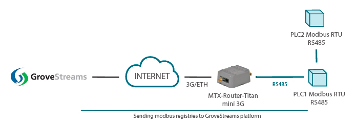
(Image: Modbus RTU PLC1/PLC2 device with an RS485 port; Sending Modbus registers to the GroveStreams platform)
Basic Configuration of the GroveStreams Platform
This Application Note is not a user guide of GroveStreams, yet an indicator of the most necessary aspects in order to view data sent by the Titan router. If you require more information relating to GroveStreams, please consult their documentation.
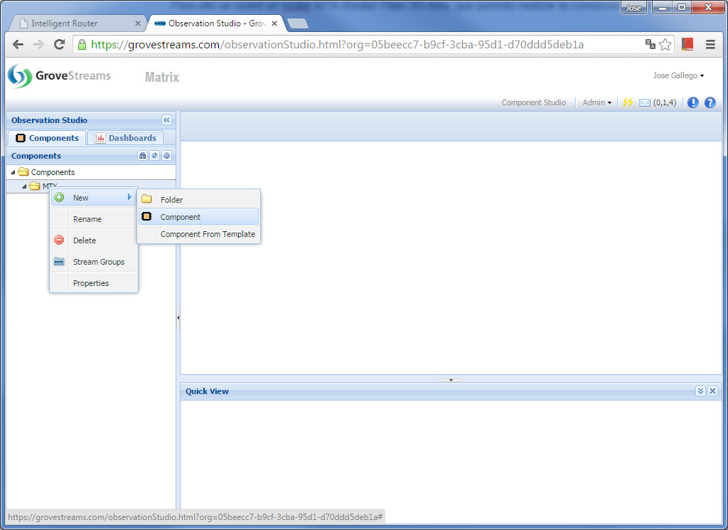
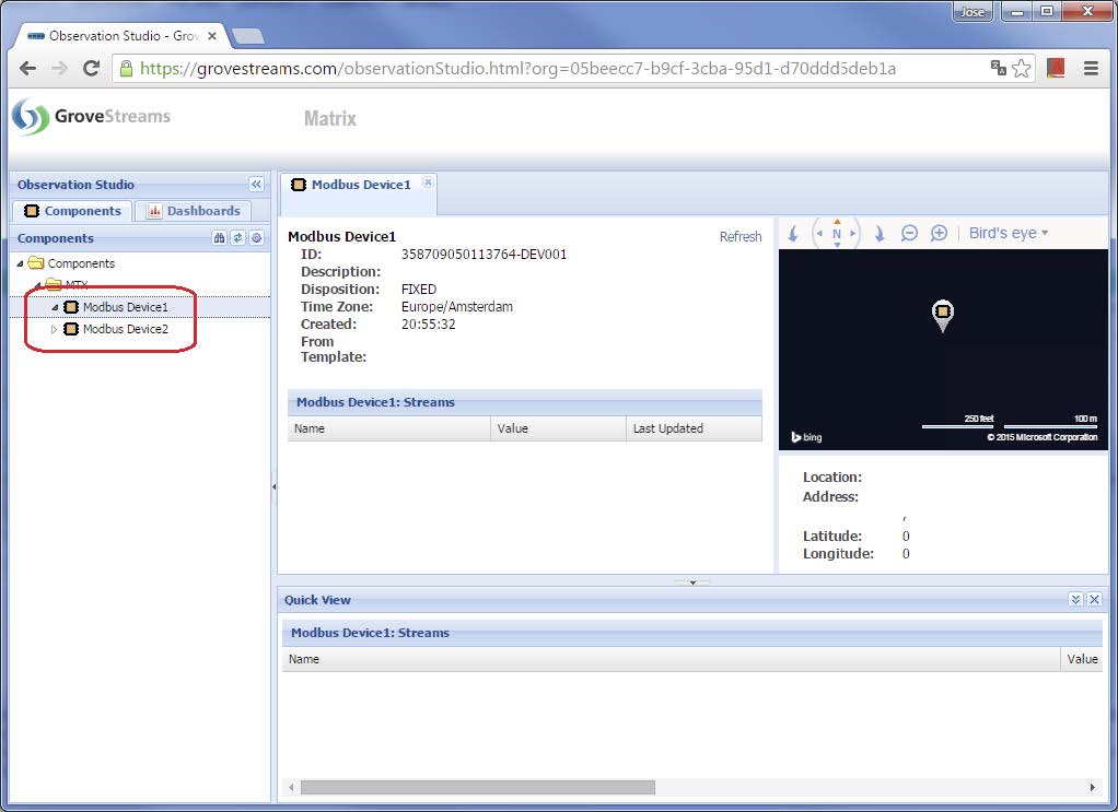
Once you have created an account with GroveStreams, you must create two devices (components) – one for the PLC1 device and another for the PLC2 device. We will name them “Modbus Device 1” and “Modbus Device 2” in the example. To do this, right click and select the option “New Component”.
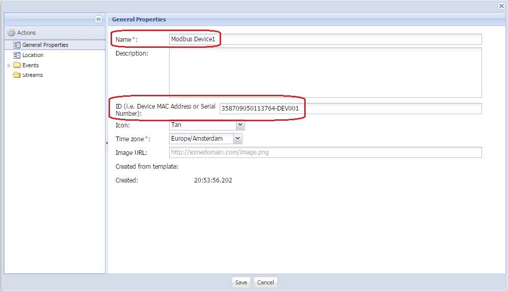
Following this, we will enter the each device’s data, namely its name and ID. The ID is a text string, also called compId, that allows GroveStreams to identify from which device it is receiving data. For this example, we will input the following: [Titan router IMEI number]-[PLC1 ID] (later we will see the ID for the PLC1 but in the meantime we will use “DEV001”), i.e. “35809050113764-DEV001”. In the following image, we can see the PLC1 device’s information.
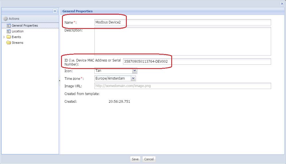
We repeat the process for the PLC2 device. We must create a new component, this time indicating the ID as [Titan router IMEI number]-[PLC2 ID] , i.e. “35809050113764-DEV002”.
Once completed, both devices will appear in the menu to the left of the screen.
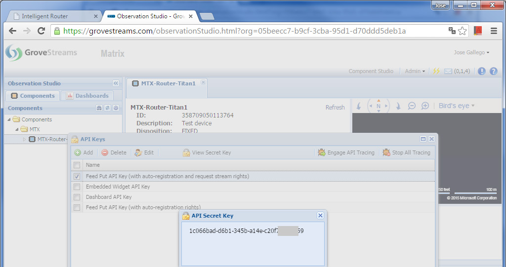
Another piece of data we require is the API KEY. This allows the GroveStreams platform to authenticate a device to send your data. Therefore, each time data is sent to the platform, the API_KEY will always also be sent with the compId, all of which will be encrypted using SSL. As a result, the API KEY should be kept secret.
In order to find out the API_KEY, click on the menu “Admin > API Keys” and take note of the number as shown in the following screen:
Configuring the Titan’s COM1 Serial Port
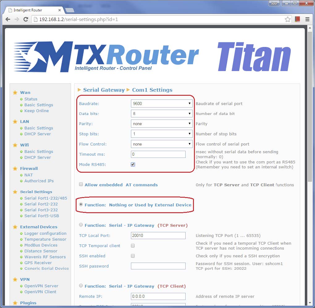
To access the Modbus device with an RS232 port we will use the Titan router’s COM1 port. For this, we must access the following configuration screen: “Serial Settings > Serial Port1-232/485” and input the configuration as shown in the screen below.
We must configure the Titan’s COM1 port in RS485 mode and with the same configuration as the interrogating Modbus port (9600,8,N,1). We must select the mode “Function: nothing or Used by External Device” since this is the port that will be used to read the external Modbus devices.
Configuring the Titan Router’s Modbus
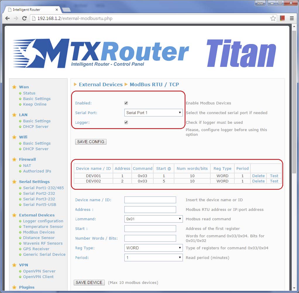
This configuration is done from the menu “External Devices > Modbus Devices”. In the main area, we should only activate “Enabled” as well as indicating that the serial port COM1 previously configured will be used for Modbus reading.
We will create two Modbus devices to be read. In the first, we will configure the 10 registers to be read from the Modbus RTU device with address @1, specifying that the first is 1. The device’s ID is DEV001 (the same as what we configured in the GroveStreams platform). Likewise, the second device with address @2, we will indicate that we want to read 10 registers starting with number 5, and that the ID is DEV002. The Modbus registers are to be read every minute in order to test the example.
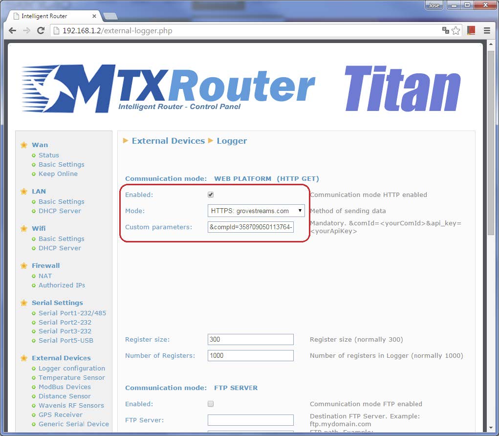
Configuring the Logger
This configuration is done from the menu “External Devices > Logger Configuration”. We must click “Enabled”, select the mode “HTTPS: groveStreams.com” and, most importantly, in custom parameters, we must input:
&compId=358709050113764-IDXXXXX&api_key=1c066bad-d6b1-345b-a14ec20f7A307d59
In other words, in &compId we must input [Titan router’s IMEI]–[text IDXXXXX], followed by the user’s API_KEY. The text IDXXXXX is very important since the Titan router will substitute this text for the corresponding ID when sending data to the GroveStreams platform. For the example, this will be DEV001 and DEV002 depending on whether data is sent from the PLC1 or PLC2 device.
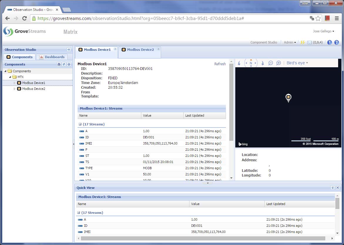
Configuring the Logger in GroveStreams
In order to test the scenario, we must reset the Titan router and wait for the first Modbus readings to take place and for these to be received in the GroveStreams platform. It is necessary to click “refresh” for each component to receive the new data.
FAQs
- In this example, readings from Modbus RTU registers are sent. Can the same be done with Modbus TCP?
Yes, it can. The Modbus RTU address must be changed to IP:502. For example, in this example we would change the “1” for something similar to “192.168.1.10:502”.

 Enter the “ethernet” or “modem” connection type:
 For an ethernet configuration, make sure the IP parameters are compatible with server access according to the concentrator local network configuration. For an ethernet connection, the configuration must be compatible with the concentrator’s local network topology so that it can access the servers. This configuration is done from the “Networks” configuration page (see section 3.2.2.3: “Networks”).
For a modem connection, the modem configuration must be correct before a connection can be set up. This configuration is done from the “Modem” configuration page (see section 3.2.2.4: “Modem”).
The parameters for the servers to be configured are at least the following:
For an ethernet configuration, make sure the IP parameters are compatible with server access according to the concentrator local network configuration. For an ethernet connection, the configuration must be compatible with the concentrator’s local network topology so that it can access the servers. This configuration is done from the “Networks” configuration page (see section 3.2.2.3: “Networks”).
For a modem connection, the modem configuration must be correct before a connection can be set up. This configuration is done from the “Modem” configuration page (see section 3.2.2.4: “Modem”).
The parameters for the servers to be configured are at least the following:
 Therefore the following fields need to be configured: “Interface”, “Type”, “Server type”, “Address”, “Port”, “Login” and “Password”.
The other fields can be left at the default values subject to the directories having been properly created beforehand. See section 3.1.2: “Configuration files” for more details.
Therefore the following fields need to be configured: “Interface”, “Type”, “Server type”, “Address”, “Port”, “Login” and “Password”.
The other fields can be left at the default values subject to the directories having been properly created beforehand. See section 3.1.2: “Configuration files” for more details.


 Wait. The concentrator will reboot using its factory configuration.


