Skip to main content
Suchen Sie etwas anderes?
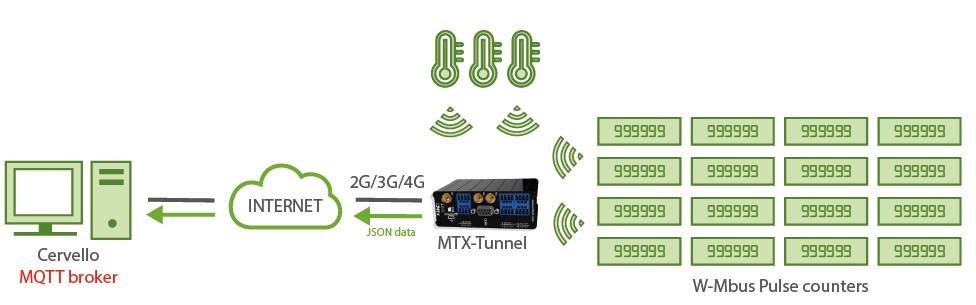
Scenario details:
- It is necessary to monitor 300 W-Mbus pulse counters from the manufacturer Adeunis and 30 temperature sensors also from the manufacturer Adeunis
- Each meter emits 1 RF frame with the count data every 1 minute, but only the W-Mbusconcentrator must store and send 1 frame every hour to the data platform. The temperature sensors send data every 30 seconds, but we only need to send the temperature every 15 minutes. In other words, the hub must configure time windows of 15 minutes. The temperature will be sent every 1 window and the water meter, every 4 time windows
- The meters will be installed in an urban area with many other W-Mbus devices nearby. Filter by manufacturer and serial number must be configured
- The data must be read and stored within the hub’s memory and automatically sent to a platform via MQTT using a JSON object whenever there is data coverage. To save data, the W-Mbus frame must be base-64 encoded
Solution: MTX-Tunnel firmware + MTX-IoT-S [4-N]
Example of configuration (config.txt file):
| Configuration | Observations |
| COMM2_baudrate: 9600 COMM2_bitsperchar: 8 COMM2_autorts: off COMM2_autocts: off COMM2_stopbits: 1 COMM2_parity: none GPRS_apn: movistar.es GPRS_login: MOVISTAR GPRS_password: MOVISTAR GPRS_timeout: 0 MTX_PIN: 0000 MTX_mode: none MTX_model: 199802407 MTX_ping: 30 MTX_pingIP: 8.8.8.8 MTX_TPServer: time1.google.com MTX_TPServer2: time2.google.com MTX_TPProtocol: ntp MTX_TPFormat: unit MTX_porAux: wmbus MTX_numGSMErrors: 180 SMS_allPhones: on SMS_sendIP: on SMS_ATEnabled: on SMS_ATResponse: on LOGGER_enabled: on LOGGER_registerSize: 1000 LOGGER_numRegistersRam: 1000 LOGGER_numRegistersFlash: 0 LOGGER_mode: mqtt LOGGER_mqttTopic: /LOGGER DNS_enabled: on DNS_mode: mqtt DNS_mqttTopic: /DNS DNS_period: 3600 WMBUS_mode:9 WMBUS_interval: 15 WMBUS_data: jsonrawhex |
Speed of serial port Data bit No flux control No flux control Stop bits Bit parity APN GPRS provided by the GSM operator GPRS Login GPRS Password Modem is always GPRS connected Pin of the SIM GPRS connection server type Modem model Ping time to oversee connection Google IP (f.e.) to ping Time server Time server backup NTP protocol Time format Auxiliar port Reset if no registration in network in 1800 secs Send SMS with commands from any phone Modem responds to a missed call/SMS Commands can be sent to the MTX by SMS MTX responds with an SMS to a command SMS MTX responds with an SMS to a command SMS Period to read counter Logger on to store readings Max. number of MTX internal registries Internal registry size Max. number of registries Sending mode via MQTT Status data sending activated MQTT sending mode Topic where status data will be sent to Every 3600 seconds a sending will be made We configure work mode 9 for Wireless MBus We set a window of 15 minutes We configure the data in base 64 (no compression) |
Details:
- The data corresponding to the counter within the JSON, will be encoded in BASE64.
Example:{“IMEI”:”354033091777774”,”TYPE”:”WMBUS”,”TS”:”2020-12-11T08:58:07Z”,”WDATA”:”174446061802001003077aef8a00002f2f0412c40900001237”}Where:
IMEI: the IMEI of the modem sending the data
TYPE: type of frame sent
TS: Timestamp of when the WMBus frame was collected in the MTX-Tunnel
WDATA: W-Mbus data in HEX format - For the correct operation of the example, a file named “wmbus.txt” must be introduced, where it is allowed to introduce different filters, in addition to the sampling period. The file “wmbus.txt” is in CSV format and must be specified like this, indicating a line for each device
<FAB>,<NUM_SERIE>,<VERSION>,<TIPO>,<PERIODO>
Where:
<FAB> (optional): ASCII. It is the name of the manufacturer, see annex D of this manual for the list of names. If not specified, it will not filter by manufacturer (unless WMBUS_filter is used)
<NUM_SERIE> (required): HEX. It is the serial number of the W-Mbus device
<VER> (optional): HEX. It is the firmware version of the device. If it is not specified, it is not filtered by this field
<TYPE> (optional): HEX. It is the type of device. If it is not specified, it is not filtered by this field
<PERIOD> (optional): DECIMAL. Period for reading frames. For example, if a 15 minute time window (WMBUS_interval: 15) is configured and <PERIOD> has a value of 4, 1 W-MBUS frame from the sensor will be captured every 15×4 = 60 minutes (1 hour). If not specified, consider period 1
Wmbus.txt file example:
ARF,10000218,,,4
ARF,2000102a,,,
…
Line 1 description:
ARF manufacturer filter (Adeunis), for a device with serial number 10000218, without specifying VERSION filter, without specifying TYPE filter and specifying a period 4 (that is, as WMBus_interval: 15, implies a reading every 15×4 = 60 minutes)
Line 2 description:
ARF manufacturer filter (Adeunis), for a device with serial number 2000102a, without specifying VERSION filter, without specifying TYPE filter and without specifying period, so period is 1 (that is, as WMBus_interval: 15, implies a reading every 15×1 = 15 minutes) - The wmbus.txt file must be entered in the modem in the same way and level as the configuration file “config.txt”, that is, in the root directory of the modem

 Enter the “ethernet” or “modem” connection type:
 For an ethernet configuration, make sure the IP parameters are compatible with server access according to the concentrator local network configuration. For an ethernet connection, the configuration must be compatible with the concentrator’s local network topology so that it can access the servers. This configuration is done from the “Networks” configuration page (see section 3.2.2.3: “Networks”).
For a modem connection, the modem configuration must be correct before a connection can be set up. This configuration is done from the “Modem” configuration page (see section 3.2.2.4: “Modem”).
The parameters for the servers to be configured are at least the following:
For an ethernet configuration, make sure the IP parameters are compatible with server access according to the concentrator local network configuration. For an ethernet connection, the configuration must be compatible with the concentrator’s local network topology so that it can access the servers. This configuration is done from the “Networks” configuration page (see section 3.2.2.3: “Networks”).
For a modem connection, the modem configuration must be correct before a connection can be set up. This configuration is done from the “Modem” configuration page (see section 3.2.2.4: “Modem”).
The parameters for the servers to be configured are at least the following:
 Therefore the following fields need to be configured: “Interface”, “Type”, “Server type”, “Address”, “Port”, “Login” and “Password”.
The other fields can be left at the default values subject to the directories having been properly created beforehand. See section 3.1.2: “Configuration files” for more details.
Therefore the following fields need to be configured: “Interface”, “Type”, “Server type”, “Address”, “Port”, “Login” and “Password”.
The other fields can be left at the default values subject to the directories having been properly created beforehand. See section 3.1.2: “Configuration files” for more details.


 Wait. The concentrator will reboot using its factory configuration.


