Titan – AN34: Connecting a USB Webcam to the Titan Router, Capturing and Sending Footage

Looking for something else?

Titan – AN34: Connecting a USB Webcam to the Titan Router, Capturing and Sending Footage

Scene Details

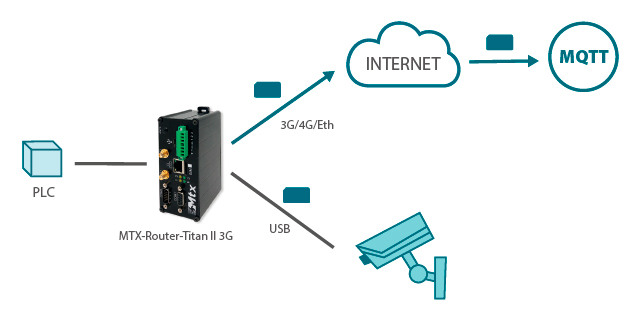
Remote control applications are more usual every day. Many of these applications need access to the footage of a remote camera. In many places there is no access to ADSL in order to connect directly an IP camera. For example solar gardens, distant stations, etc. In these cases we need a 3G/4G router to allow remote access.

This application note is a quick guide with step by step examples on how to use and connect an USB webcam to an MTX-Router-Titan II 3G. After reading this note you will know how to capture footage and send it via MQTT.

Hardware Needed

  • MTX-Router-Titan II 3G with antenna and power chord
  • USB webcam
  • USB-micro USB (OTG) cable adaptor USB
  • 3G/4G data SIM card

MTX-Router-Titan 3G WAN Configuration

To configure the router we connect it to our PC. Then we open our Internet browser. The router has a default static IP address 192.168.1.2, so we will need to configure our PC with a static IP within the range of 192.168.1.X, for example we configure the LAN address 192.168.1.10 on our PC.

Then we go to http://192.168.1.2 to go directly to the next start screen of the router configuration.

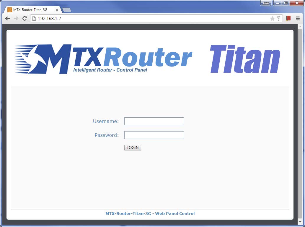
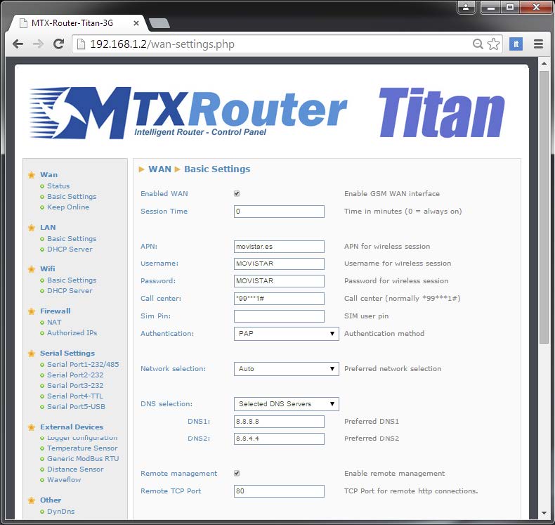
The default username and password are “admin” and “admin.” We will start by configuring the network parameters for the SIM card we are using. To do that we go to “Wan > Basic settings.

Configuring Titan for the Reading of Modbus Devices

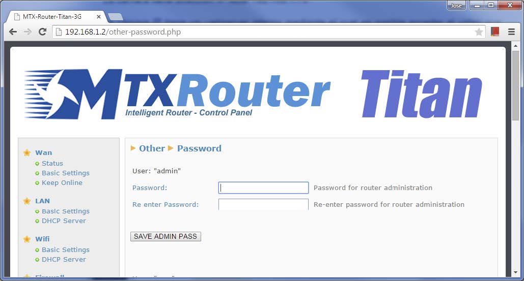
Then we need to change the password. To do that we go to “Other > Password” and click on “Save Admin Pass” to save the changes.

Configuration of the MQTT Section of the Router Titan

We are going to configure the MQTT service of the Titan router. We need to do this because the footage will be transmitted this way. To do that we need to access the section Other > Mqtt:

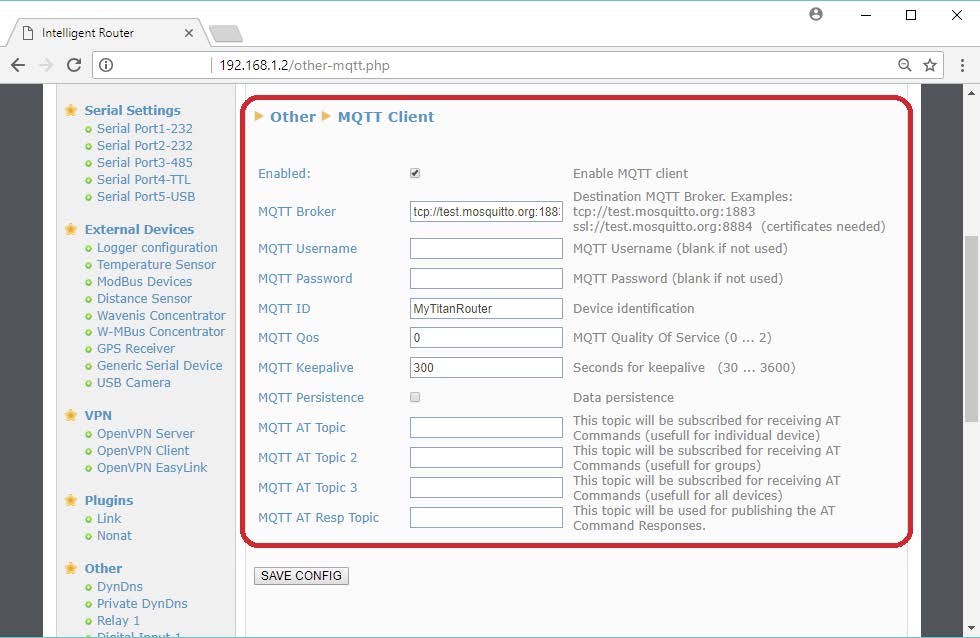
We will specify the following: click the box “Enable” to activate the service, the MQTT Broker we use, and the MQTT ID to identify our router. We click on “SAVE CONFIG.”

Taking a Picture Every Min. and Sending it Automatically via MQTT

In this configuration, we make the Titan router to take a snap every minute and to send it via MQTT. It is a simple process and it is done from the section “External Devices > USB Camera.”

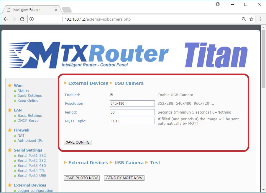
On this section, we enable the service clicking on the box “Enabled,” we specify the picture resolution (in this case 640x480px), we specify the capture and sending period (the value of 60 on the example specifies one delivery every 60 seconds) and then we configure the TOPIC mqtt where the picture will be sent (on this example the topic is FOTO). We click on “SAVE CONFIG” to finish the configuration.

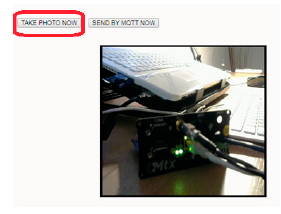
You can make a test and click on the button “TAKE A PHOTO NOW.” If it works, in a few seconds we should see the captured image on the lower part of that same screen.

Now we can restart the router and we should be receiving an image via MQTT every minute, once the Titan router has IP connectivity.

Footage Format

Titan router transmits the image via MQTT in this format:

nombreImagen,tamañoImagenEnBytes,[array bytes de la imagen jpeg]

That is, the MQTT message brought to your broker is divided in 3 fields separated by “,” The first one is the name of the image file. The second one is the size of the image file in bytes, and the last parameter is an array of bytes with all the raw content of the image in jpeg.

Capturing and Sending Footage via AT Commands

An important feature of the Titan router is that it is possible to make almost anything via AT commands. We could also take a picture and send it with AT commands. These AT commands can be sent as usual: via Telnet, SSH, HTTP Rest, SMS, Modbus TCP, Modbus RTU, SNMP, etc.

For example, imagine a PLC that takes a picture when it receives data from a sensor, and then sends the picture via MQTT. We would need to send a couple of AT commands via TCP or RTU Modbus to the Titan router (check Application Note 10 to learn how to send AT commands via modbus).

The AT command that allows capturing an image is:

AT^MTXTUNNEL=GETUSBPHOTO

Once this AT command is sent, the router will capture a picture in a few seconds. It will senda n “OK” or “ERROR” depending on the success of the capturing.

The AT commands that allows sending the last capture image is:

AT^MTXTUNNEL=SENDUSBPHOTOMQTT,topic

Once the AT command is sent, the image will be sent via MQTT to the topic specified on the field “topic” of said AT command.

Do you have a question? Need a quote? Please contact us.

  • This field is for validation purposes and should be left unchanged.

Appendices and other documents

Annexes et autres documents

Appendices and other documents

Appendices and other documents

Appendices and other documents

Appendices and other documents

Appendices and other documents

Appendices and other documents

Appendices and other documents

FAQ

No, the concentrator is not able to decrypt data from WM-BUS equipment because it does not have a safe on board to guarantee the security of the encryption keys of your equipment. The recovered data is deposited without modification (without decryption) by the concentrator on your remote server.
Please check these items in this order:
  • the battery level: if the battery level is too low or empty, the product will not run properly or not run at all.
  • Modem reception level: a bad signal at the modem may also prevent the hub from uploading files. Look to move the product or install an external antenna to improve signal quality.
  • The last configuration file: a bad configuration file can block the product.

Remotely, by checking the regularly uploaded files if the product configuration is correct.

On site, by passing the magnet over the product, you will hear 3 short beeps.

Replace the product and inject the configuration from the old product into the new one. If a white list is used, remember to inject it into the new product as well.

Appendices and other documents

Other manuals

Application Notes

FAQ

Gateway configuration:

Start by checking that the computer’s IP parameters are compatible with the WebdynSunPM IP address (by default 192.168.1.12)

Launch a web browser (Chrome, Firefox, Edge, Safari, etc.) and enter the WebdynSunPM concentrator IP address in the address bar. An authentication page is displayed:

The default accesses are:

IdentifiantMot de passe
userhighhigh

Click “Login”

There are two configuration solutions, using the web interface and using text messages:
  • Configuration using the web interface:
Start by establishing a connection to the concentrator by connecting to it to access the server configuration: Enter the “ethernet” or “modem” connection type: For an ethernet configuration, make sure the IP parameters are compatible with server access according to the concentrator local network configuration. For an ethernet connection, the configuration must be compatible with the concentrator’s local network topology so that it can access the servers. This configuration is done from the “Networks” configuration page (see section 3.2.2.3: “Networks). For a modem connection, the modem configuration must be correct before a connection can be set up. This configuration is done from the “Modem” configuration page (see section 3.2.2.4: “Modem). The parameters for the servers to be configured are at least the following: Therefore the following fields need to be configured: “Interface”, “Type”, “Server type”, “Address”, “Port”, “Login” and “Password”. The other fields can be left at the default values subject to the directories having been properly created beforehand. See section 3.1.2: “Configuration files for more details.
  • Text message configuration:
Text message configuration requires sending the following commands:
      • Apn: to configure the SIM card APN. (see section 3.2:“apn” modem configuration command)
      • Ftp: to configure the FTP server that will contain the concentration configuration (see section 3.3: “ftp” FTP configuration command”).
      • Connect: to launch the connection to the FTP server and load the configuration (see section 3.1: ““connect” connection command

Access to the FTP server depends on the selected solution.

If you have chosen a portal, it will give you the FTP server access identifiers.

If you want to use your own FTP server, contact your network administrator.

For all other configurations, and to determine the best solution, contact the Webdyn sales department which will advise you and direct you to the relevant contacts: contact@webdyn.com

General gateway use

There are 2 methods to force a concentrator factory reset:
  • Press the Factory Reset button on the concentrator for 20 seconds:
Wait. The concentrator will reboot using its factory configuration.
  • If a SIM card is installed and configured, a “factory” text message can also be used for factory reset. Just send the “factory” text message to the SIM card phone number (see section 3.7: “factory” reset command”)

It is possible to send commands to connected devices if they accept them.

The WebdynSunPM can store up to 50Mb of uncompressed data per declared device.

If there is no access to the remote server, the WebdynSunPM concentrator can store the data for several months.

The maximum data storage time varies depending on the amount of data to be collected and the configured collection frequency.

The average storage time varies from 3 to 4 months.

The average service life of the battery is 5 years.

It may vary depending on the installation environment.

All our products are guaranteed for 2 years.

For more information, read the general terms and conditions of sale.

The data volume depends on the exchanged files.

The average is about 5 MB per month but this varies from one installation to another.

Inverter compatibility

See section 1.4: “Supported devices”.

Modbus device compatibility:

Yes, different Modbus devices can be connected to the same serial port.

Device compatibility:

    • Same type of RS485 or 4 wire connection.
    • All devices should be able to be configured using identical bus specifications. Same speed, same parity, same number of stop bits and data bits on all devices and on the WebdynSunPM.
    • Each device must be assigned a unique Modbus address (between 1 and 247) on the bus. (UnitID)

Appendices and other documents

FAQ

CONFIGURATION OF THE WEBDYNSUN GATEWAY

  • Start by checking that your computer’s IP parameters are compatible with the WebdynSun’s “IP” address (the default is 192.168.1.12). 
  • Next, launch a web browser (Firefox or IE) and enter the WebdynSun’s IP address in the address bar. An authentication page will appear: 

The default accesses are:
Username: userhigh
Password: high

  • Click on “log in”  

There are two types of configuration: via the web interface or via SMS.

Configuration of the web interface:

1/ Go to the configuration page with the gateway IP address (default 192.168.1.12)

2/ Go to the Configuration tab.

3/ Select either the Ethernet or modem connection mode:

If connecting via the local network (Ethernet):

  • Edit the WebdynSun’s IP parameters by assigning it a network-compatible address.

Please note, all fields must be completed in accordance with the configuration of your local network.

If connecting via the GPRS network (Modem):

  • Change the connection settings of the GPRS modem to the settings provided by your mobile operator.

4/ Edit the FTP server parameters.

5/ Confirm the changes.

6/ Restart the WebdynSun gateway using the new settings.

7/ In the menu, click on the “installation” tab, followed by the “connection” sub-tab and start the connection.

Configuration via SMS:

This configuration method requires the use of an active SIM card with a data option and a pin code that must be either “0000” or disabled.
The SIM card must be inserted into the unit before connection to the mains supply.
After connection to the mains supply, send the following SMS messages to the number of the previously inserted SIM card:

SMS for configuring the APN:
After replacing the generic fields with those of your operator, send the following SMS*:
apn=apn_name;usr=user_name;pwd=password;

Replace the above SMS fields with the following information:

  • apn_name: APN name supplied by your mobile operator
  • user_name: APN ID supplied by your mobile operator
  • password: APN password supplied by your mobile operator

SMS for FTP configuration:
After replacing the generic fields with those of your FTP server, send the following SMS*:
Ftp=server_name:user_name:password:port;

Replace the above SMS fields with the following information:

  • server_name: FTP server address
  • user_name: FTP account ID
  • Password: FTP account password
  • Port: FTP server port (the default port is 21)

Connection SMS:

Send the word “connect” by SMS* to launch a connection to the FTP server

*Please note: the formatting of the SMS must be exactly identical to that shown above (e.g.: no spaces between characters, etc.)

There are 2 ways of resetting the gateway.

  • If connecting by Ethernet:
    • Disconnect from the mains
    • Remove the cover
    • Disconnect the battery
    • Put the DIP Switch 2 on the WebdynSun card in “ON” position
    • Start the WebdynSun by connecting it only to the mains power supply
    • Wait until all the LEDs flash and then stop flashing (3 to 5 mins).
    • Disconnect from the mains
    • Reset the Dip Switch 2 to “OFF” 
    • Reconnect the battery
    • Reconnect to the mains supply and the WebdynSun starts normally.
  • If there is a SIM card inserted in the unit:
    • Send an SMS message containing the word “factory” to the number of the inserted SIM card.

NB : Resetting the gateway restores the configuration to its original state. Please note: data will be saved but the specific settings will not. Therefore, all the settings must be reconfigured.

Commands can be sent to connected devices with the exception of certain inverters and Modbus slaves that do not accept write requests.

If the device allows it, command files can be created on the FTP server.

The WebdynSun has a memory of about 100MB.

Therefore, if the remote server cannot be accessed, the WebdynSun gateway can backup data for several months.
The maximum data backup time varies depending on the amount of data to be collected.

The average backup time ranges from 3 to 4 months.

The average battery life is 5 years.

It may vary depending on the installation environment.

Yes, data may be sent to a PLC if the latter is equipped with a Modbus protocol.
The “Report” configuration file allows the WebdynSun gateway to automatically write the values read on a Modbus slave

All our products are guaranteed for 2 years.

For further information, please see our general conditions of sale.

Files uploaded by the WebdynSun gateway are compressed in Gz format.

The data contained in these files is structured in csv format.

The data volume depends on the files exchanged.

The average is about 5 MB per month but this varies from one installation to another.

INVERTER COMPATIBILITY WITH THE WEBDYNSUN GATEWAY

Different brands of inverter may be connected to the RS485(B) port or via the Ethernet port if the inverter protocol is based on the Modbus protocol (RTU or TCP).

However, different brands of inverters cannot be connected to the same RS485(A) port.

For a list of compatible inverters, please see the product page of the WebdynSun data gateway
  • Check if the correct inverter protocol is selected before starting detection:
  • Check the wiring and configuration of the inverters by referring to the inverter appendices.
  • Check that the inverters are not in OFF or stand-by mode.
  • Check that the line end plugs on the RS 485(A) Bus are turned on.

COMPATIBILITY WITH MODBUS DEVICES

Yes, any device you wish to connect must be configured and its Modbus definition file must be created.

The configuration is mainly based on the RS485 serial bus parameters and the IP parameters.

Yes, different Modbus devices can be connected to the same RS485 (B) port.

However, they must have the same communication parameters (bus parameters or compatible IP parameters), in order for them to communicate with each other.

Appendices and other documents

Appendices and other documents

Appendices and other documents

Appendices and other documents

Appendices and other documents

  • Warning – Firmware update V4.07.02 For the old version with SIM CARD of the pin code is 0000 you can update in this version. For the second case : When you insert a SIM CARD with pin code is 0000 used in this version (4.07.02) Downgrading to a previous version is not permitted.

Appendices and other documents

  • Warning – Firmware update V4.07.02 – For the old version with SIM CARD of the pin code is 0000 you can update in this version.

    For the second case : When you insert a SIM CARD with pin code is 0000 used in this version (4.07.02) Downgrading to a previous version is not permitted.

Annexes and other documents

FAQ

Annexes and other documents

FAQ

Annexes and other documents

FAQ

Annexes and other documents

FAQ

CONFIGURATION OF THE WEBDYNRF GATEWAY

  • If the file is deleted from the directory after connecting the WebdynRF gateway, the problem is usually due to a file format error. The configuration and control files must follow the format described in the schema (XSD) files. To check schema consistency, open the XML file with the Notepad++ text editor and install the “XML Tool” add-on. Next, copy the corresponding XSD file to the XML file in the same directory, and select “Validate now” in XML Tool. Errors detected by the tool should be displayed.
  • If the file is not deleted from the server, the most common problem is that the file has not been located correctly. The file must be available on the server in the “INBOX” directory and in the sub-directory bearing the product UID name (e.g.: “/INBOX/0045CE/”).

GENERAL USE OF THE WEBDYNRF GATEWAY

The amount of data exchanged on the GPRS network varies depending on the configuration. However, the average consumption would be about 5MB / month.
The WebdynRF gateway consumes an average of about 250mA.

There are 2 firmware updating methods:
Local updating:
On the WebdynRF configuration interface, go to the “Actions” tab and select the updater in the “File upload” menu before clicking on the “Upload” button

Remote updating:
Upload the file containing the updater (file with extension “.bz2”) in the “BIN” directory to the FTP server . Next, place the update command in the INBOX directory corresponding to your gateway (“INBOX/”, with, the identifier of the gateway concerned)

The update command must follow the following format:

      updater.tar.bz2
      checksum_md5

updater.tar.bz2
checksum_md5

With:

  • updater.tar.bz2: Updater file name uploaded to the “BIN” directory
  • checksum_md5: Md5 code of the updater file

A lack of connection to the FTP server may be due to a network connection problem (Ethernet or GPRS), an FTP login problem or a failure to initiate the connection.

If you cannot connect to the network, check the following points:

  • Ethernet:
    • Modem set to “off” or “always off”
    • “Gateway” fields correctly entered
    • At least one DNS server must be configured
  • GPRS:
    • Modem set to “on”
    • APN, APN ID and APN password correctly entered
    • GPRS call number set to “*99***1#”

If you cannot log in, check the following points:

  • Incorrect FTP parameters
  • TCP port 21 closed at output
  • Domain name resolution problem: the DNS server is not specified

If the connection fails to initiate:

In this case, only the automatic connection does not work. The problem is probably caused by an incorrect schedule configuration. Please note, the schedule ID must be an integer.

 PARTICULAR APPLICATION OF THE WEBDYNRF WIRELESS M-BUS GATEWAY

For the WM-bus module data to be transmitted, you must:

  • Choose the mode corresponding to the modules used (S, T or N)
  • Define the modules or groups of modules to be processed

A module may be defined in a unique way by all the fields below:

  • Id
  • Manufacturer
  • Version
  • Medium

If a module’s data is encrypted, the encryption key for this module can be defined in the “Key” field.

To simplify the entry of the modules to be processed, a module group can be defined that conforms to the fields entered. The other fields will then be left empty (below is an example of a configuration for retrieving all Webdyn manufacturer (WDN) modules with the encryption key “00000000000000000000000000000000”.

  •   Id :
  •   Manufacturer : WDN
  •   Medium :
  •   Version :
  •   Label : Webdyn
  •   Key : 00000000000000000000000000000000

Note: In order for the modules (filters) entered to be taken into account, the “ByPass filter” mode must be deactivated.

Click here to read the media file 

Click here to read the units file 

 PARTICULAR APPLICATION OF THE WEBDYNRF WAVENIS

The tool is connected to the gateway via the installer access (install).

It is therefore necessary to use the installer password (default is “middle”), and not the administrator’s password (default is “high”)

The statuses transmitted by the WebdynRF gateway are the raw values contained in the Wavenis modules. They are transmitted without interpretation. For further details, please refer to the Coronis module manuals.

Appendix and other documents

FAQ

CONFIGURATION OF THE WEBDYNRF GATEWAY

  • If the file is deleted from the directory after connecting the WebdynRF gateway, the problem is usually due to a file format error. The configuration and control files must follow the format described in the schema (XSD) files. To check schema consistency, open the XML file with the Notepad++ text editor and install the “XML Tool” add-on. Next, copy the corresponding XSD file to the XML file in the same directory, and select “Validate now” in XML Tool. Errors detected by the tool should be displayed.
  • If the file is not deleted from the server, the most common problem is that the file has not been located correctly. The file must be available on the server in the “INBOX” directory and in the sub-directory bearing the product UID name (e.g.: “/INBOX/0045CE/”).

GENERAL USE OF THE WEBDYNRF GATEWAY

The amount of data exchanged on the GPRS network varies depending on the configuration. However, the average consumption would be about 5MB / month.
The WebdynRF gateway consumes an average of about 250mA.

There are 2 firmware updating methods:
Local updating:
On the WebdynRF configuration interface, go to the “Actions” tab and select the updater in the “File upload” menu before clicking on the “Upload” button

Remote updating:
Upload the file containing the updater (file with extension “.bz2”) in the “BIN” directory to the FTP server . Next, place the update command in the INBOX directory corresponding to your gateway (“INBOX/”, with, the identifier of the gateway concerned)

The update command must follow the following format:

      updater.tar.bz2
      checksum_md5

updater.tar.bz2
checksum_md5

With:

  • updater.tar.bz2: Updater file name uploaded to the “BIN” directory
  • checksum_md5: Md5 code of the updater file

A lack of connection to the FTP server may be due to a network connection problem (Ethernet or GPRS), an FTP login problem or a failure to initiate the connection.

If you cannot connect to the network, check the following points:

  • Ethernet:
    • Modem set to “off” or “always off”
    • “Gateway” fields correctly entered
    • At least one DNS server must be configured
  • GPRS:
    • Modem set to “on”
    • APN, APN ID and APN password correctly entered
    • GPRS call number set to “*99***1#”

If you cannot log in, check the following points:

  • Incorrect FTP parameters
  • TCP port 21 closed at output
  • Domain name resolution problem: the DNS server is not specified

If the connection fails to initiate:

In this case, only the automatic connection does not work. The problem is probably caused by an incorrect schedule configuration. Please note, the schedule ID must be an integer.

 PARTICULAR APPLICATION OF THE WEBDYNRF WIRELESS M-BUS GATEWAY

For the WM-bus module data to be transmitted, you must:

  • Choose the mode corresponding to the modules used (S, T or N)
  • Define the modules or groups of modules to be processed

A module may be defined in a unique way by all the fields below:

  • Id
  • Manufacturer
  • Version
  • Medium

If a module’s data is encrypted, the encryption key for this module can be defined in the “Key” field.

To simplify the entry of the modules to be processed, a module group can be defined that conforms to the fields entered. The other fields will then be left empty (below is an example of a configuration for retrieving all Webdyn manufacturer (WDN) modules with the encryption key “00000000000000000000000000000000”.

  •   Id :
  •   Manufacturer : WDN
  •   Medium :
  •   Version :
  •   Label : Webdyn
  •   Key : 00000000000000000000000000000000

Note: In order for the modules (filters) entered to be taken into account, the “ByPass filter” mode must be deactivated.

Click here to read the media file 

Click here to read the units file 

 PARTICULAR APPLICATION OF THE WEBDYNRF WAVENIS

The tool is connected to the gateway via the installer access (install).

It is therefore necessary to use the installer password (default is “middle”), and not the administrator’s password (default is “high”)

The statuses transmitted by the WebdynRF gateway are the raw values contained in the Wavenis modules. They are transmitted without interpretation. For further details, please refer to the Coronis module manuals.

Annexes et autres documents

  • WARNING :  Pour les anciens produits qui disposent d’une carte SIM avec un code PIN à 0000 , la mise à jour vers la version 4.07.02 sera fonctionelle.

    Second cas : Si la carte SIM avec un code PIN à 0000 est utilisée dans cette version (4.07.02), le passage vers une mise à jour antérieure est interdit.