Suchen Sie etwas anderes?
Scenario details:
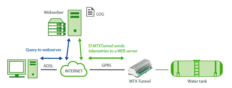
- We want to monitor a water tank level. To do this, an analog input of a GPRS modem will be used. The modem will be always connected to GPRS and will use a dynamic IP address
- The modem must take a measurement every 5 minutes and send it to a Web server via GPRS using HTTP GET to create a LOG file with the daily consumption statistics
- Access the modem’s internal web server to check the status of the tank in real time. from the internal webserver act over a relay which allows the flow entry into the tank. The access to the webserver won’t have a firewall (from any IP) but will be protected by a username and password
Solution: MTX-Tunnel firmware + MTX-Java-IoT/MTX-Java-T/MTX-Java-T2
Config.txt configuration file:
| Configuration | Observations |
|
GPRS_apn: movistar.es |
GPRS APN form your network operator GPRS Login GPRS Password Google DNS. Must be used if TCP_IP is set to DNS Value 0 means MTX-Tunnel is always GPRS connected If SIM card has no PIN security, use 0000 value MTX-Terminal modem model MTX-DIN GPRS-Serial tunnel gateway is not needed URC messages aren’t needed Time synchronization protocol Time server (MTX synchronizes the time) Time server backup Every 35 min. without communications, one ping Address where ping is made Firewall disabled MTX logger activated, to store readings Where the data frame come from URL where the JSON data will be sent Size of the MTX internal registry Max. registries inside MTX Sending data HTTP GET (JSON) Every 5 minutes sends data from E/S WebServer service feature enabled WebServer access login WebServer access password WebServer Skin Script GSM positioning |
Details:
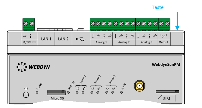
- Remember the descriptions E/S of the MTX-4G-Java-IoT-STD-N-RL
- Example of the JSON received by the webserver:
{“IMEI”:354033090131429,”TS”:”23/12/18 11:09:59”,”TYPE”:”IOS”,”P”:”12345678”,”IO1” :0,”IO2”:0,”IO3”:0,”IO4”:0,“IO5”:1,”IO6”:0,”IO7”:0,”IO8”:0,”IO9”:0,”IO10”:0,”AD1”:0, ”AD2”:0,”CO1”:“0”,”CO2”:”0”,”CO3”:”0”}
Where:
IMEI: indicates the modem IMEI
TS: timestamp of the date reading in the modem
TYPE: data frame kind (IOS)
P: field indicated in LOGGER_password
IOx: x digital I/O (check Annex 10 to know which are used by this equipment. They are IO1, …
IO6 in case of the relay model)
ADx: digital input 1 and 2 (values from 0 to 50000)
COx: pulse counter 1 and 2 (GPIO1, GPIO2 and GPIO3)

 Geben Sie den Verbindungsmodus „ethernet“ oder „modem“ ein:
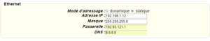
 Stellen Sie bei einer Ethernet-Konfiguration sicher, dass die IP-Parameter mit dem Serverzugriff entsprechend der lokalen Netzwerkkonfiguration des Hubs kompatibel sind. Bei einer Ethernet-Verbindung muss die Konfiguration mit der lokalen Netztopologie des Hubs kompatibel sein, damit dieser auf die Server zugreifen kann. Diese Konfiguration erfolgt über die Konfigurationsseite „Networks“ (siehe Kapitel 3.2.2.3: „Netzwerke (Networks)“).
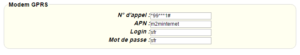
Bei einer Modemverbindung muss das Modem korrekt konfiguriert sein, bevor eine Verbindung hergestellt werden kann. Diese Konfiguration erfolgt auf der Konfigurationsseite „Modem“ (siehe Kapitel 3.2.2.4: „Modem“).
Die minimal zu konfigurierenden Serverparameter sind folgende:
Stellen Sie bei einer Ethernet-Konfiguration sicher, dass die IP-Parameter mit dem Serverzugriff entsprechend der lokalen Netzwerkkonfiguration des Hubs kompatibel sind. Bei einer Ethernet-Verbindung muss die Konfiguration mit der lokalen Netztopologie des Hubs kompatibel sein, damit dieser auf die Server zugreifen kann. Diese Konfiguration erfolgt über die Konfigurationsseite „Networks“ (siehe Kapitel 3.2.2.3: „Netzwerke (Networks)“).
Bei einer Modemverbindung muss das Modem korrekt konfiguriert sein, bevor eine Verbindung hergestellt werden kann. Diese Konfiguration erfolgt auf der Konfigurationsseite „Modem“ (siehe Kapitel 3.2.2.4: „Modem“).
Die minimal zu konfigurierenden Serverparameter sind folgende:
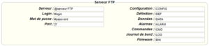
 Diese Felder müssen konfiguriert werden: „Interface“, „Type“, „Server type“, „Address“, „Port“, „Login“ und „Password“.
In den übrigen Feldern können die Standardwerte beibehalten werden, solange die Verzeichnisse zuvor korrekt angelegt wurden. Weitere Einzelheiten siehe Kapitel 3.1.2: „Konfigurationsdateien“.
Diese Felder müssen konfiguriert werden: „Interface“, „Type“, „Server type“, „Address“, „Port“, „Login“ und „Password“.
In den übrigen Feldern können die Standardwerte beibehalten werden, solange die Verzeichnisse zuvor korrekt angelegt wurden. Weitere Einzelheiten siehe Kapitel 3.1.2: „Konfigurationsdateien“.


 Warten Sie. Der Hub startet nach ein paar Augenblicken mit der Werkseinstellung neu.