Vai al contenuto principale
Suchen Sie etwas anderes?
The Titan routers are GPS enabled and can be ordered with an internal GPS module built in. These devices (MTX-Router-Titan-3G-mini-GPS or MTX-Router-Titan-4G-mini-GPS) can also be used with an external GPS module by connecting it to either the microUSB port or a serial port.
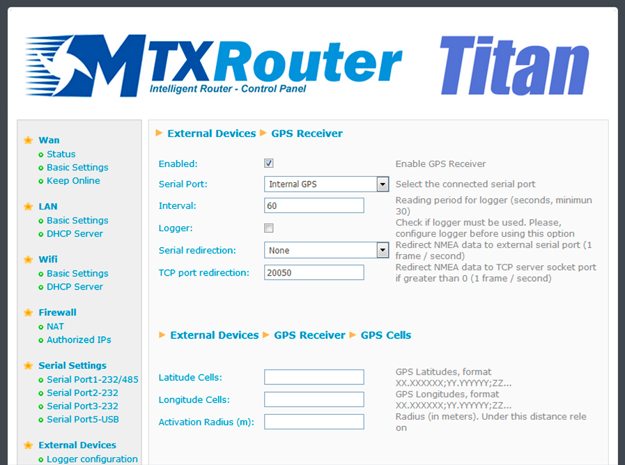
- Enabled: activate this option if we have an internal (or external) GPS module connected to the Titan router to be used
- Serial Port: select the MTX-Router-Titan II, MTX-Router-Titan and MTX-Router-Titan mini’s serial port used to connect the GPS. For the MTX-Router-Titan-3G device using an internal GPS module, select “Serial Port 4 TTL”. For the MTX-Router-Titan-3G-mini-GPS or MTX-Router-Titan-4G-mini-GPS devices, select “Internal GPS”
- Interval: select the period (in seconds) of GPS readings taken. A value greater than 30 seconds must be specified
- Logger: activate this option if we wish to save the GPS positions that are read in the internal logger for later sending to a web platform via HTTP or FTP. This is useful if we are using the Titan device to implement a fleet management system using GPS
- Output redirection: this option allows NMEA position frames to be redirected through one of the RS232, RS485 serial ports or the USB port of the Titan device. In this way, GPS can be used by an additional serial port device
- TCP Port Redirection: in the same way NMEA frames can be obtained via an RS232 or RS485 serial port or the USB port, it is also possible to obtain NMEA frames via a TCP socket by connecting to the Titan device by Ethernet, WiFi, 3G or 4G. If a TCP port greater than 0 is specified, the device will connect to said TCP port and obtain the NMEA frames
GPS Cells
Titan routers allow we to specify up to 20 GPS cells defined by longitude, latitude and radius. For example, a relay can be programmed to be activated when inside a GPS cell and deactivated when outside. This is useful to detect when machinery leaves the work area or to impede the opening of electronic lock system controlled containers outside loading areas, etc.
- Latitude cells: in this field we should state the latitude of the different GPS cells to be configured, separating them by a semi-colon
- Longitude cells: in this field we should state the longitude of the different GPS cells to be configured, separating them by a semi-colon
- Activation radius: in this field we should state the radius of the different GPS cells to be configured, separating them by a semi-colon
ADDITIONAL NOTES
- Once the configuration is complete, press the “SAVE CONFIG” button to save the changes. Remember that the router should be reset in order for the changes to take effect.

 Enter the “ethernet” or “modem” connection type:
 For an ethernet configuration, make sure the IP parameters are compatible with server access according to the concentrator local network configuration. For an ethernet connection, the configuration must be compatible with the concentrator’s local network topology so that it can access the servers. This configuration is done from the “Networks” configuration page (see section 3.2.2.3: “Networks”).
For a modem connection, the modem configuration must be correct before a connection can be set up. This configuration is done from the “Modem” configuration page (see section 3.2.2.4: “Modem”).
The parameters for the servers to be configured are at least the following:
For an ethernet configuration, make sure the IP parameters are compatible with server access according to the concentrator local network configuration. For an ethernet connection, the configuration must be compatible with the concentrator’s local network topology so that it can access the servers. This configuration is done from the “Networks” configuration page (see section 3.2.2.3: “Networks”).
For a modem connection, the modem configuration must be correct before a connection can be set up. This configuration is done from the “Modem” configuration page (see section 3.2.2.4: “Modem”).
The parameters for the servers to be configured are at least the following:
 Therefore the following fields need to be configured: “Interface”, “Type”, “Server type”, “Address”, “Port”, “Login” and “Password”.
The other fields can be left at the default values subject to the directories having been properly created beforehand. See section 3.1.2: “Configuration files” for more details.
Therefore the following fields need to be configured: “Interface”, “Type”, “Server type”, “Address”, “Port”, “Login” and “Password”.
The other fields can be left at the default values subject to the directories having been properly created beforehand. See section 3.1.2: “Configuration files” for more details.


 Wait. The concentrator will reboot using its factory configuration.


